
 Facebook
 Google
 GitHub
 Linkedin
DC Electric Circuits
Series-Parallel DC Circuits
41 questions By Tony R. Kuphaldt
-
Question 19 of 41
Calculate the amount of voltage dropped across resistor R2:

Also, note the direction of current through it and the polarity of the voltage drop across it.
Reveal answerVR2 = 12.11 volts, positive on top and negative on bottom. If you follow conventional flow notation, this means current goes down through resistor R2. The actual flow of electrons through R2, however, is up.
Notes:Discuss with your students how they obtained their answers for this question. The reasoning and procedures are far more important than the actual answer itself.
Students often have difficulty formulating a method of solution: determining what steps to take to get from the given conditions to a final answer. While it is helpful at first for you (the instructor) to show them, it is bad for you to show them too often, lest they stop thinking for themselves and merely follow your lead. A teaching technique I have found very helpful is to have students come up to the board (alone or in teams) in front of class to write their problem-solving strategies for all the others to see. They don’t have to actually do the math, but rather outline the steps they would take, in the order they would take them.
By having students outline their problem-solving strategies, everyone gets an opportunity to see multiple methods of solution, and you (the instructor) get to see how (and if!) your students are thinking. An especially good point to emphasize in these “open thinking” activities is how to check your work to see if any mistakes were made.
-
Question 20 of 41
Antique American automobiles often used 6 volt electrical systems instead of the 12 volt components found in more modern cars and trucks. People who restore these old vehicles may have difficulty finding old 6-volt generators and batteries to replace the defective, original units. An easy solution is to update the vehicle’s generator and battery with modern (12 volt) components, but then another problem arises.
A 12 volt generator and 12 volt battery will overpower the old 6 volt headlights, brake lights, and other electrical “loads” in the vehicle. A solution used by antique automobile restorers is to connect resistors between the 12-volt generator system and the 6-volt loads, like this:

Explain why this solution works, and also discuss some of the disadvantages of using resistors to adapt the new (12 volt) to the old (6 volt) components.
Reveal answerThe purpose of the resistors is to “drop” half the voltage supplied by the generator and battery, so that the loads (light bulbs, in this case) receive only 6 volts instead of 12 volts. A disadvantage of using resistors to do this is that the resistors waste a lot of electrical power in the form of heat.
Notes:Make sure your students understand the concept of a “load:” any electrical or electronic component that uses power from an electrical source. Usually, “loads” are the end-use components of a circuit: light bulbs, motors, solenoids, speakers, etc. In this case, the resistors could be considered loads as well as the light bulbs, but since the light bulbs are the only components performing useful work from the power source, it is customary to think of them when the word “load” is used, rather than the resistors.
-
Question 21 of 41
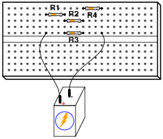
Draw a schematic diagram of this “breadboarded” circuit:
Reveal answer
Notes:If your students are not yet aware of how solderless breadboard holes are connected together, this is a good time to introduce them!





How did you guys find the answer for Q5, figure 6