
 Facebook
 Google
 GitHub
 Linkedin
DC Electric Circuits
Series-Parallel DC Circuits
41 questions By Tony R. Kuphaldt
-
Question 16 of 41
In this series-parallel circuit, resistors R1 and R2 are in series with each other, but resistor R3 is neither in series nor in parallel with either R1 or R2:

Normally, the first step in mathematically analyzing a circuit such as this is to determine the total circuit resistance. In other words, we need to calculate how much resistance the voltage source “sees” in the network formed by R1, R2, and R3. If the circuit were a simple series configuration, our task would be easy:

Likewise, if the circuit were a simple parallel configuration, we would have no difficulty at all calculating total resistance:

Due to the fact that our given circuit is neither purely series nor purely parallel, though, calculation of total resistance is not a simple one-step operation. However, there is a way we could simplify the circuit to something that is either simple series or simple parallel. Describe how that might be done, and demonstrate using numerical values for resistors R1, R2, and R3.
Reveal answerSuppose we had these resistor values:
- • R1 = 3000 Ω
- • R2 = 2000 Ω
- • R3 = 5000 Ω
The total resistance in this case would be 2500 Ω. I’ll let you figure out how to do this!
Hint: 2.5k is exactly one-half of 5k
Notes:Figuring out how to calculate total resistance in a series-parallel network is an exercise in problem-solving. Students must determine how to convert a complex problem into multiple, simpler problems which they can then solve with the tools they have.
This sort of exercise is also helpful in getting students to think in terms of incremental problem-solving. Being able to take sections of a circuit and reduce them to equivalent component values so that the circuit becomes simpler and simpler to analyze is a very important skill in electronics.
-
Question 17 of 41
Rank these five light bulb assemblies according to their total electrical resistance (in order of least to greatest), assuming that each of the bulbs is the same type and rating:
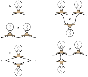
Explain how you determined the relative resistances of these light bulb networks.
Reveal answer- • C (least total resistance)
- • D
- • A
- • E
- • B (greatest total resistance)
Notes:I prefer to enter discussion on series and parallel circuits prior to introducing Ohm’s Law. Conceptual analysis tends to be more difficult than numerical analysis in electric circuits, but is a skill worthwhile to build, especially for the sake of effective troubleshooting.
It is effective after conceptual (qualitative) analysis, though, to go through a numerical (quantitative) analysis of a circuit like this to prove that the concepts are correct, if the students are advanced enough at this point to do series-parallel resistance calculations.
-
Question 18 of 41
Determine the amount of electrical resistance indicated by an ohmmeter connected between the following points in this circuit:
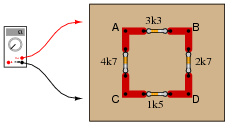
- • Between points A and B =
- • Between points A and C =
- • Between points C and D =
- • Between points D and B =
- • Between points B and C =
Explain whether or not it makes any sense to speak of a “total” resistance for this network.
Reveal answer- • Between points A and B = 2.41 kΩ
- • Between points A and C = 2.89 kΩ
- • Between points C and D = 1.32 kΩ
- • Between points D and B = 2.10 kΩ
- • Between points B and C = 2.75 kΩ
Notes:The purpose of this question is to get students to realize that the resistance “looking into” different areas of a resistive network depends on what those areas are.





How did you guys find the answer for Q5, figure 6