Facebook
 Google
 GitHub
 Linkedin
Digital Circuits
Switched Capacitor Circuitry
15 questions By Tony R. Kuphaldt
-
Question 13 of 15
A 4.7 μF capacitor (Ci) is charged to a voltage of 4 volts, then connected to the inverting input of an operational amplifier (with a 10 μF feedback capacitor, Cf). What happens to the voltages across Ci and Cf? Explain your answer in detail.
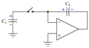
Reveal answerVCi goes to zero, while VCf increases by 1.88 volts.
Notes:The reason why VCi goes to zero, of course, is a function of the opamp’s negative feedback. This aspect of the question provides an excellent opportunity for review of basic opamp principles.
-
Question 14 of 15
Many switched capacitor circuits require non-overlapping, two-phase clock signals. Shown here is a schematic diagram of a gate circuit that converts a single clock signal into two complementary, non-overlapping clock signals:
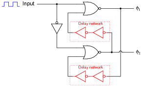
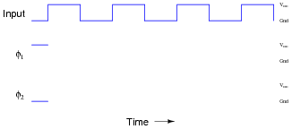
Assume that the only gates possessing propagation delays are the double-NOT gates (inside the dotted boxes), whose sole purpose it is to provide a short time delay in the feedback signals. Draw a timing diagram showing the two-phase clock signals (φ1 and φ2) in relation to the input clock waveform, and be prepared to explain how and why this circuit works:
Reveal answer
Notes:Although it will be obvious to many of your students, you might want to ask “why do we call the two clock signals non-overlapping?” What, exactly, would an overlapping set of clock signals look like, in comparison?
-
Question 15 of 15
The fact that switched capacitor networks can behave equivalently to resistors is exploited in a variety of integrated circuits. At first, this may seem strange, as switched capacitor networks generally require at least two switching transistors and a two-phase, non-overlapping clock (in addition to the capacitor itself) in order to function, which seems like a lot of peripheral circuitry compared to a single resistor. What possible advantage is there to using switched capacitor networks in integrated circuits instead of resistors? Support your answer with research, if possible.
Reveal answerSwitched capacitor networks are not just resistor equivalents, they are variable resistor equivalents. Also, these networks actually tend to be smaller than integrated circuit resistors, and are less prone to drift.
There are other advantages to switched capacitor networks, but these are just some of the basic reasons behind their prevalence in modern integrated circuits.
Notes:Ask your students to explain why switched capacitor networks are less prone to drift than resistors constructed on a semiconductor substrate. Just focus on one source of drift, such as temperature, to simplify the topic. What effect does temperature have on a semiconducting resistor, and why? What effect does temperature have on a capacitor built of semiconductor layers separated by an insulating layer, and why? With discrete components, are capacitors more stable over time than resistors? Why or why not?