
 Facebook
 Google
 GitHub
 Linkedin
Analog Integrated Circuits
Linear Computational Circuitry
35 questions By Tony R. Kuphaldt
-
Question 28 of 35
∫f(x) dx Calculus alert!
You are part of a team building a rocket to carry research instruments into the high atmosphere. One of the variables needed by the on-board flight-control computer is velocity, so it can throttle engine power and achieve maximum fuel efficiency. The problem is, none of the electronic sensors on board the rocket has the ability to directly measure velocity. What is available is an altimeter, which infers the rocket’s altitude (it position away from ground) by measuring ambient air pressure; and also an accelerometer, which infers acceleration (rate-of-change of velocity) by measuring the inertial force exerted by a small mass.The lack of a “speedometer” for the rocket may have been an engineering design oversight, but it is still your responsibility as a development technician to figure out a workable solution to the dilemma. How do you propose we obtain the electronic velocity measurement the rocket’s flight-control computer needs?
Reveal answerOne possible solution is to use an electronic integrator circuit to derive a velocity measurement from the accelerometer’s signal. However, this is not the only possible solution!
Notes:This question simply puts students’ comprehension of basic calculus concepts (and their implementation in electronic circuitry) to a practical test.
-
Question 29 of 35
∫f(x) dx Calculus alert!
A Rogowski Coil is essentially an air-core current transformer that may be used to measure DC currents as well as AC currents. Like all current transformers, it measures the current going through whatever conductor(s) it encircles.Normally transformers are considered AC-only devices, because electromagnetic induction requires a changing magnetic field (\(\frac{dφ}{dt}\)) to induce voltage in a conductor. The same is true for a Rogowski coil: it produces a voltage only when there is a change in the measured current. However, we may measure any current (DC or AC) using a Rogowski coil if its output signal feeds into an integrator circuit as shown:
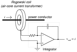
Connected as such, the output of the integrator circuit will be a direct representation of the amount of current going through the wire.
Explain why an integrator circuit is necessary to condition the Rogowski coil’s output so that output voltage truly represents conductor current.
Reveal answerThe coil produces a voltage proportional to the conductor current’s rate of change over time (vcoil = M [di/dt]). The integrator circuit produces an output voltage changing at a rate proportional to the input voltage magnitude ([(dvout)/dt] ∝ vin). Substituting algebraically:
dvout dt= M di dtReview question: Rogowski coils are rated in terms of their mutual inductance (M). Define what “mutual inductance” is, and why this is an appropriate parameter to specify for a Rogowski coil.
Follow-up question: the operation of a Rogowski coil (and the integrator circuit) is probably easiest to comprehend if one imagines the measured current starting at 0 amps and linearly increasing over time. Qualitatively explain what the coil’s output would be in this scenario and then what the integrator’s output would be.
Challenge question: the integrator circuit shown here is an “active” integrator rather than a “passive” integrator. That is, it contains an amplifier (an “active” device). We could use a passive integrator circuit instead to condition the output signal of the Rogowski coil, but only if the measured current is purely AC. A passive integrator circuit would be insufficient for the task if we tried to measure a DC current - only an active integrator would be adequate to measure DC. Explain why.
Notes:This question provides a great opportunity to review Faraday’s Law of electromagnetic induction, and also to apply simple calculus concepts to a practical problem. The coil’s natural function is to differentiate the current going through the conductor, producing an output voltage proportional to the current’s rate of change over time (vout ∝ [(diin)/dt]). The integrator’s function is just the opposite. Discuss with your students how the integrator circuit “undoes” the natural calculus operation inherent to the coil (differentiation).
The subject of Rogowski coils also provides a great opportunity to review what mutual inductance is. Usually introduced at the beginning of lectures on transformers and quickly forgotten, the principle of mutual inductance is at the heart of every Rogowski coil: the coefficient relating instantaneous current change through one conductor to the voltage induced in an adjacent conductor (magnetically linked).
v2 = M di1 dtUnlike the iron-core current transformers (CT’s) widely used for AC power system current measurement, Rogowski coils are inherently linear. Being air-core devices, they lack the potential for saturation, hysteresis, and other nonlinearities which may corrupt the measured current signal. This makes Rogowski coils well-suited for high frequency (even RF!) current measurements, as well as measurements of current where there is a strong DC bias current in the conductor. By the way, this DC bias current may be “nulled” simply by re-setting the integrator after the initial DC power-up!
If time permits, this would be an excellent point of departure to other realms of physics, where op-amp signal conditioning circuits can be used to “undo” the calculus functions inherent to certain physical measurements (acceleration vs. velocity vs. position, for example).
-
Question 30 of 35
∫f(x) dx Calculus alert!
A Rogowski coil has a mutual inductance rating of 5 μH. Calculate the size of the resistor necessary in the integrator circuit to give the integrator output a 1:1 scaling with the measured current, given a capacitor size of 4.7 nF: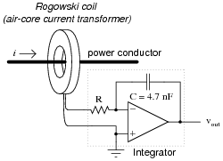
That is, size the resistor such that a current through the conductor changing at a rate of 1 amp per second will generate an integrator output voltage changing at a rate of 1 volt per second.
Reveal answerR = 1.064 kΩ
Notes:This question not only tests students’ comprehension of the Rogowski coil and its associated calculus (differentiating the power conductor current, as well as the need to integrate its output voltage signal), but it also tests students’ quantitative comprehension of integrator circuit operation and problem-solving technique. Besides, it gives some practical context to integrator circuits!



very good worksheets