
 Facebook
 Google
 GitHub
 Linkedin
Analog Integrated Circuits
Linear Computational Circuitry
35 questions By Tony R. Kuphaldt
-
Question 31 of 35
Practical integrator circuits must have a compensating resistor connected in parallel with the capacitor, in the feedback loop. Typically, this resistor value is very large: about 100 times as large as Rin.
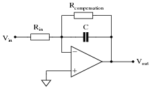
Describe why this is a necessity for accurate integration. Hint: an ideal opamp would not need this resistor!
Reveal answerThis compensation resistor helps offset errors otherwise incurred by the opamp’s bias current on the inverting input.
Notes:Discuss where bias currents originate from in the opamp’s internal circuitry, and ask your students if they have any recommendations on specific opamp types that minimize bias current.
-
Question 32 of 35
Practical op-amp integrator and differentiator circuits often cannot be built as simply as their “textbook” forms usually appear:
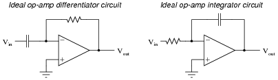
The voltage gains of these circuits become extremely high at certain signal frequencies, and this may cause problems in real circuitry. A simple way to “tame” these high gains to moderate levels is to install an additional resistor in each of the circuits, as such:

The purpose of each resistor is to “dominate” the impedance of the RC network as the input signal frequency approaches the point at which problems would occur in the ideal versions of the circuits. In each of these “compensated” circuits, determine whether the value of the compensation resistor needs to be large or small compared to the other resistor, and explain why.
Of course, this solution is not without problems of its own. By adding this new resistor to each circuit, a half-power (-3 dB) cutoff frequency point is created by the interaction of the compensation resistor and the capacitor, as predicted by the equation fc = [1/(2 πRcompC)]. The value predicted by this equation establishes a practical limit for the differentiation and integration functions, respectively. Operating on the wrong side of the frequency limit will result in an output waveform that is not the true time-derivative or time-integral of the input waveform. Determine whether the fc value constitutes a low frequency limit or a high frequency limit for each circuit, and explain why.
Reveal answerFor the differentiator circuit, Rcomp << R
feedback, and [1/(2 πRcompC)] is a high frequency limit.
For the integrator circuit, Rcomp >> Rinput, and [1/(2 πRcompC)] is a low frequency limit.
Notes:In order to successfully answer the questions, students will need a firm grasp on the nature of the gain problem with differentiator and integrator circuits. This is based on an understanding of capacitive reactance, and the relationship between op-amp gain and input/feedback impedances. These are not difficult questions to answer, if one takes an orderly and methodical approach to the problem. Help your students reason through to the correct answers by asking questions that challenge them to link concepts of op-amp feedback gain, capacitive reactance, impedances of series and parallel RC networks, etc.
-
Question 33 of 35
∫f(x) dx Calculus alert!
The chain rule of calculus states that:dx dydy dz= dx dzSimilarly, the following mathematical principle is also true:
dx dy= dx dzdy dzIt is very easy to build an opamp circuit that differentiates a voltage signal with respect to time, such that an input of x produces an output of [dx/dt], but there is no simple circuit that will output the differential of one input signal with respect to a second input signal.
However, this does not mean that the task is impossible. Draw a block diagram for a circuit that calculates [dy/dx], given the input voltages x and y. Hint: this circuit will make use of differentiators.
Challenge question: draw a full opamp circuit to perform this function!
Reveal answer
Notes:Differentiator circuits are very useful devices for making “live” calculations of time-derivatives for variables represented in voltage form. Explain to your students, for example, that the physical measurement of velocity, when differentiated with respect to time, is acceleration. Thus, a differentiator circuit connected to a tachogenerator measuring the speed of something provides a voltage output representing acceleration.
Being able to differentiate one signal in terms of another, although equally useful in physics, is not so easy to accomplish with opamps. A question such as this one highlights a practical use of calculus (the “chain rule”), where the differentiator circuit’s natural function is exploited to achieve a more advanced function.



very good worksheets