
 Facebook
 Google
 GitHub
 Linkedin
Analog Integrated Circuits
Linear Computational Circuitry
35 questions By Tony R. Kuphaldt
-
Question 19 of 35
The purpose of this circuit is to provide a pushbutton-adjustable voltage. Pressing one button causes the output voltage to increase, while pressing the other button causes the output voltage to decrease. When neither button is pressed, the voltage remains stable. Essentially, it is an active integrator circuit, with resistors R1 and R2 and capacitor C1 setting the rates of integration:

After working just fine for quite a long while, the circuit suddenly fails: now it only outputs zero volts DC all the time. Identify at least one component or wiring failure that would account for the circuit’s faulty behavior, and explain why that fault would cause the circuit to act like this.
Reveal answerThe wire connecting the junction of R1 and R2 with the inverting input of the opamp could be broken open. Also, C1 could be failed shorted.
Challenge question: why do you suppose I specify a CA3130 operational amplifier for this particular circuit? What is special about this opamp that qualifies it for the task?
Notes:I purposely omitted the explanations for the possible faults listed in the answer, because I want the students to think this through, and to do so in class with you present so you may hear their reasoning.
-
Question 20 of 35
∫f(x) dx Calculus alert!
Integrator circuits may be understood in terms of their response to DC input signals: if an integrator receives a steady, unchanging DC input voltage signal, it will output a voltage that changes with a steady rate over time. The rate of the changing output voltage is directly proportional to the magnitude of the input voltage: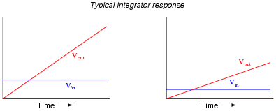
A symbolic way of expressing this input/output relationship is by using the concept of the derivative in calculus (a rate of change of one variable compared to another). For an integrator circuit, the rate of output voltage change over time is proportional to the input voltage:
dVout dt∝ Vin A more sophisticated way of saying this is, “The time-derivative of output voltage is proportional to the input voltage in an integrator circuit.” However, in calculus there is a special symbol used to express this same relationship in reverse terms: expressing the output voltage as a function of the input. For an integrator circuit, this special symbol is called the integration symbol, and it looks like an elongated letter “S”:
Vout ∝ ⌠ ⌡ T 0 Vin dt Here, we would say that output voltage is proportional to the time-integral of the input voltage, accumulated over a period of time from time=0 to some point in time we call T.
“This is all very interesting,” you say, “but what does this have to do with anything in real life?” Well, there are actually a great deal of applications where physical quantities are related to each other by time-derivatives and time-integrals. Take this water tank, for example:
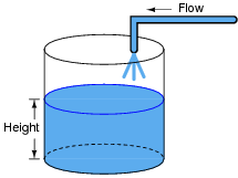
One of these variables (either height H or flow F, I’m not saying yet!) is the time-integral of the other, just as Vout is the time-integral of Vin in an integrator circuit. What this means is that we could electrically measure one of these two variables in the water tank system (either height or flow) so that it becomes represented as a voltage, then send that voltage signal to an integrator and have the output of the integrator derive the other variable in the system without having to measure it!
Your task is to determine which variable in the water tank scenario would have to be measured so we could electronically predict the other variable using an integrator circuit.
Reveal answerFlow (F) is the variable we would have to measure, and that the integrator circuit would time-integrate into a height prediction.
Notes:Your more alert students will note that the output voltage for a simple integrator circuit is of inverse polarity with respect to the input voltage, so the graphs should really look like this:

I have chosen to express all variables as positive quantities in order to avoid any unnecessary confusion as students attempt to grasp the concept of time integration.
-
Question 21 of 35
∫f(x) dx Calculus alert!
We know that the output of an integrator circuit is proportional to the time-integral of the input voltage:
Vout ∝ ⌠ ⌡ T 0 Vin dt But how do we turn this proportionality into an exact equality, so that it accounts for the values of R and C? Although the answer to this question is easy enough to simply look up in an electronics reference book, it would be great to actually derive the exact equation from your knowledge of electronic component behaviors! Here are a couple of hints:
I = V Ri = C dv dtReveal answerVout = − 1 RC⌠ ⌡ T 0 Vin dt Follow-up question: why is there a negative sign in the equation?
Notes:The two “hint” equations given at the end of the question beg for algebraic substitution, but students must be careful which variable(s) to substitute! Both equations contain an I, and both equations also contain a V. The answer to that question can only be found by looking at the schematic diagram: do the resistor and capacitor share the same current, the same voltage, or both?







very good worksheets