
 Facebook
 Google
 GitHub
 Linkedin
Analog Integrated Circuits
Linear Computational Circuitry
35 questions By Tony R. Kuphaldt
-
Question 22 of 35
∫f(x) dx Calculus alert!
If an object moves in a straight line, such as an automobile traveling down a straight road, there are three common measurements we may apply to it: position (x), velocity (v), and acceleration (a). Position, of course, is nothing more than a measure of how far the object has traveled from its starting point. Velocity is a measure of how fast its position is changing over time. Acceleration is a measure of how fast the velocity is changing over time.These three measurements are excellent illustrations of calculus in action. Whenever we speak of “rates of change,” we are really referring to what mathematicians call derivatives. Thus, when we say that velocity (v) is a measure of how fast the object’s position (x) is changing over time, what we are really saying is that velocity is the “time-derivative” of position. Symbolically, we would express this using the following notation:
v = dx dtLikewise, if acceleration (a) is a measure of how fast the object’s velocity (v) is changing over time, we could use the same notation and say that acceleration is the time-derivative of velocity:
a = dv dtSince it took two differentiations to get from position to acceleration, we could also say that acceleration is the second time-derivative of position:
a = d2x dt2“What has this got to do with electronics,” you ask? Quite a bit! Suppose we were to measure the velocity of an automobile using a tachogenerator sensor connected to one of the wheels: the faster the wheel turns, the more DC voltage is output by the generator, so that voltage becomes a direct representation of velocity. Now we send this voltage signal to the input of a differentiator circuit, which performs the time-differentiation function on that signal. What would the output of this differentiator circuit then represent with respect to the automobile, position or acceleration? What practical use do you see for such a circuit?
Now suppose we send the same tachogenerator voltage signal (representing the automobile’s velocity) to the input of an integrator circuit, which performs the time-integration function on that signal (which is the mathematical inverse of differentiation, just as multiplication is the mathematical inverse of division). What would the output of this integrator then represent with respect to the automobile, position or acceleration? What practical use do you see for such a circuit?
Reveal answerThe differentiator’s output signal would be proportional to the automobile’s acceleration, while the integrator’s output signal would be proportional to the automobile’s position.
a ∝ dv dtOutput of differentiator x ∝ ⌠ ⌡ T 0 v dt Output of integrator Follow-up question: draw the schematic diagrams for these two circuits (differentiator and integrator).
Notes:The calculus relationships between position, velocity, and acceleration are fantastic examples of how time-differentiation and time-integration works, primarily because everyone has first-hand, tangible experience with all three. Everyone inherently understands the relationship between distance, velocity, and time, because everyone has had to travel somewhere at some point in their lives. Whenever you as an instructor can help bridge difficult conceptual leaps by appeal to common experience, do so!
-
Question 23 of 35
∫f(x) dx Calculus alert!
A familiar context in which to apply and understand basic principles of calculus is the motion of an object, in terms of position (x), velocity (v), and acceleration (a). We know that velocity is the time-derivative of position (v = \(\frac{dx}{dt}\)) and that acceleration is the time-derivative of velocity (a = \(\frac{dv}{dt}\)). Another way of saying this is that velocity is the rate of position change over time, and that acceleration is the rate of velocity change over time.It is easy to construct circuits which input a voltage signal and output either the time-derivative or the time-integral (the opposite of the derivative) of that input signal. We call these circuits “differentiators” and ïntegrators,” respectively.
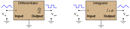
Integrator and differentiator circuits are highly useful for motion signal processing, because they allow us to take voltage signals from motion sensors and convert them into signals representing other motion variables. For each of the following cases, determine whether we would need to use an integrator circuit or a differentiator circuit to convert the first type of motion signal into the second:
- Converting velocity signal to position signal: (integrator or differentiator?)
- Converting acceleration signal to velocity signal: (integrator or differentiator?)
- Converting position signal to velocity signal: (integrator or differentiator?)
- Converting velocity signal to acceleration signal: (integrator or differentiator?)
- Converting acceleration signal to position signal: (integrator or differentiator?)
Also, draw the schematic diagrams for these two different circuits.
Reveal answer- Converting velocity signal to position signal: (integrator)
- Converting acceleration signal to velocity signal: (integrator)
- Converting position signal to velocity signal: (differentiator)
- Converting velocity signal to acceleration signal: (differentiator)
- Converting acceleration signal to position signal: (two integrators!)
I’ll let you figure out the schematic diagrams on your own!
Notes:The purpose of this question is to have students apply the concepts of time-integration and time-differentiation to the variables associated with moving objects. I like to use the context of moving objects to teach basic calculus concepts because of its everyday familiarity: anyone who has ever driven a car knows what position, velocity, and acceleration are, and the differences between them.
One way I like to think of these three variables is as a verbal sequence:

Arranged as shown, differentiation is the process of stepping to the right (measuring the rate of change of the previous variable). Integration, then, is simply the process of stepping to the left.
Ask your students to come to the front of the class and draw their integrator and differentiator circuits. Then, ask the whole class to think of some scenarios where these circuits would be used in the same manner suggested by the question: motion signal processing. Having them explain how their schematic-drawn circuits would work in such scenarios will do much to strengthen their grasp on the concept of practical integration and differentiation.
-
Question 24 of 35
This active integrator circuit processes the voltage signal from an accelerometer, a device that outputs a DC voltage proportional to its physical acceleration. The accelerometer is being used to measure the acceleration of an athlete’s foot as he kicks a ball, and the job of the integrator is to convert that acceleration signal into a velocity signal so the researchers can record the velocity of the athlete’s foot:
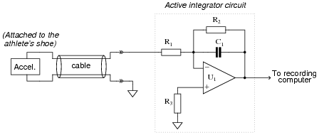
During the set-up for this test, a radar gun is used to check the velocity of the athlete’s foot as he does come practice kicks, and compare against the output of the integrator circuit. What the researchers find is that the integrator’s output is reading a bit low. In other words, the integrator circuit is not integrating fast enough to provide an accurate representation of foot velocity.
Determine which component(s) in the integrator circuit may have been improperly sized to cause this calibration problem. Be as specific as you can in your answer(s).
Reveal answerResistor R1 may be too large, and/or capacitor C1 may be too large.
Notes:This is an interesting, practical question regarding the use of an integrator circuit for real-life signal processing. Ask your students to explain their reasoning as they state their proposed component faults.
Incidentally, if anyone asks what the purpose of R2 or R3 is, tell them that both are used for opamp bias current compensation. An ideal opamp would not require these components to be in place.





very good worksheets