Facebook
 Google
 GitHub
 Linkedin
AC Electric Circuits
Series-Parallel Combination AC Circuits
26 questions By Tony R. Kuphaldt
-
Question 13 of 26
Determine the current through the series LR branch in this series-parallel circuit:

Hint: convert the series LR sub-network into a parallel equivalent first.
Reveal answerILR = 3.290 mA
Notes:Yes, that is an AC current source shown in the schematic! In circuit analysis, it is quite common to have AC current sources representing idealized portions of an actual component. For instance current transformers (CT’s) act very close to ideal AC current sources. Transistors in amplifier circuits also act as AC current sources, and are often represented as such for the sake of analyzing amplifier circuits.
Although there are other ways to calculate this voltage drop, it is good for students to learn the method of series-parallel sub-circuit equivalents. If for no other reason, this method has the benefit of requiring less tricky math (no complex numbers needed!).
Have your students explain the procedures they used to find the answer, so that all may benefit from seeing multiple methods of solution and multiple ways of explaining it.
-
Question 14 of 26
Test leads for DC voltmeters are usually just two individual lengths of wire connecting the meter to a pair of probes. For highly sensitive instruments, a special type of two-conductor cable called coaxial cable is generally used instead of two individual wires. Coaxial cable - where a center conductor is “shielded” by an outer braid or foil that serves as the other conductor - has excellent immunity to induced “noise” from electric and magnetic fields:
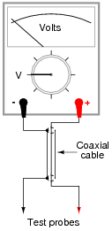
When measuring high-frequency AC voltages, however, the parasitic capacitance and inductance of the coaxial cable may present problems. We may represent these distributed characteristics of the cable as “lumped” parameters: a single capacitor and a single inductor modeling the cable’s behavior:
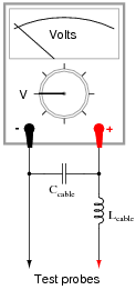
Typical parasitic values for a 10-foot cable would be 260 pF of capacitance and 650 μH of inductance. The voltmeter itself, of course, is not without its own inherent impedances, either. For the sake of this example, let’s consider the meter’s “input impedance” to be a simple resistance of 1 MΩ.
Calculate what voltage the meter would register when measuring the output of a 20 volt AC source, at these frequencies:
- f = 1 Hz ; Vmeter =
- f = 1 kHz ; Vmeter =
- f = 10 kHz ; Vmeter =
- f = 100 kHz ; Vmeter =
- f = 1 MHz ; Vmeter =
Reveal answer- f = 1 Hz ; Vmeter = 20 V
- f = 1 kHz ; Vmeter = 20 V
- f = 10 kHz ; Vmeter = 20.01 V
- f = 100 kHz ; Vmeter = 21.43 V
- f = 1 MHz ; Vmeter = 3.526 V
Follow-up question: explain why we see a “peak” at 100 kHz. How can the meter possibly see a voltage greater than the source voltage (20 V) at this frequency?
Notes:As your students what this indicates about the use of coaxial test cable for AC voltmeters. Does it mean that coaxial test cable is unusable for any measurement application, or may we use it with little or no concern in some applications? If so, which applications are these?
-
Question 15 of 26
The voltage measurement range of a DC instrument may easily be “extended” by connecting an appropriately sized resistor in series with one of its test leads:
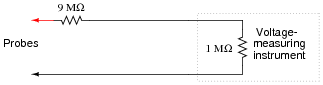
In the example shown here, the multiplication ratio with the 9 MΩ resistor in place is 10:1, meaning that an indication of 3.5 volts at the instrument corresponds to an actual measured voltage of 35 volts between the probes.
While this technique works very well when measuring DC voltage, it does not do so well when measuring AC voltage, due to the parasitic capacitance of the cable connecting the test probes to the instrument (parasitic cable inductance has been omitted from this diagram for simplicity):
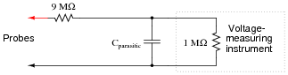
To see the effects of this capacitance for yourself, calculate the voltage at the instrument input terminals assuming a parasitic capacitance of 180 pF and an AC voltage source of 10 volts, for the following frequencies:
- f = 10 Hz ; Vinstrument =
- f = 1 kHz ; Vinstrument =
- f = 10 kHz ; Vinstrument =
- f = 100 kHz ; Vinstrument =
- f = 1 MHz ; Vinstrument =
The debilitating effect of cable capacitance may be compensated for with the addition of another capacitor, connected in parallel with the 9 MΩ range resistor. If we are trying to maintain a voltage division ratio of 10:1, this “compensating” capacitor must be 1/9 the value of the capacitance parallel to the instrument input:

Re-calculate the voltage at the instrument input terminals with this compensating capacitor in place. You should notice quite a difference in instrument voltages across this frequency range!
- f = 10 Hz ; Vinstrument =
- f = 1 kHz ; Vinstrument =
- f = 10 kHz ; Vinstrument =
- f = 100 kHz ; Vinstrument =
- f = 1 MHz ; Vinstrument =
Complete your answer by explaining why the compensation capacitor is able to “flatten” the response of the instrument over a wide frequency range.
Reveal answerWith no compensating capacitor:
- f = 10 Hz ; Vinstrument = 1.00 V
- f = 1 kHz ; Vinstrument = 0.701 V
- f = 10 kHz ; Vinstrument = 97.8 mV
- f = 100 kHz ; Vinstrument = 9.82 mV
- f = 1 MHz ; Vinstrument = 0.982 mV
With the 20 pF compensating capacitor in place:
- f = 10 Hz ; Vinstrument = 1.00 V
- f = 1 kHz ; Vinstrument = 1.00 V
- f = 10 kHz ; Vinstrument = 1.00 V
- f = 100 kHz ; Vinstrument = 1.00 V
- f = 1 MHz ; Vinstrument = 1.00 V
Hint: without the compensating capacitor, the circuit is a resistive voltage divider with a capacitive load. With the compensating capacitor, the circuit is a parallel set of equivalent voltage dividers, effectively eliminating the loading effect.
Follow-up question: as you can see, the presence of a compensation capacitor is not an option for a high-frequency, 10:1 oscilloscope probe. What safety hazard(s) might arise if a probe’s compensation capacitor failed in such a way that the probe behaved as if the capacitor were not there at all?
Notes:Explain to your students that “×10” oscilloscope probes are made like this, and that the “compensation” capacitor in these probes is usually made adjustable to create a precise 9:1 match with the combined parasitic capacitance of the cable and oscilloscope.
Ask your students what the usable “bandwidth” of a home-made ×10 oscilloscope probe would be if it had no compensating capacitor in it.

Related Tools:
- Algebraic Substitution for Electric Circuits
- Performance-Based Assessments for Basic Electricity Competencies