Facebook
 Google
 GitHub
 Linkedin
Digital Circuits
CMOS Logic Gates
27 questions By Tony R. Kuphaldt
-
Question 10 of 27
Here is a schematic diagram for a simple electronic combination lock, controlling power to a door lock solenoid:
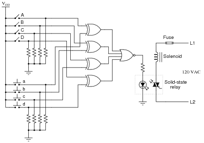
The four pushbutton switches (a, b, c, and d) are accessible to the person wishing to enter the door. The four toggle switches (A, B, C, and D) are located behind the door, and are used to set the code necessary for entering.
Explain how this system is supposed to work. What are the logic states of the respective gate outputs when a matching code is entered through the pushbutton switches? How about when a non-matching code is entered?
Do you see any security problems with this door lock circuit? How easy would it be for someone to enter, who does not know the four-bit code? Do you have any suggestions for improving this lock design?
Reveal answerThe most obvious problem with this door lock system is the small number of possible codes. It would be rather easy (especially for someone adept at counting in binary!) to simply try all the possible combinations until they gained access.
Here is what I recommend as a strategy for improving the level of security offered by this system: install a fifth pushbutton switch as an “Enter” key. If someone enters the correct four-bit code and then pushes the “Enter” button, the door will open. However, if someone enters the wrong four-bit code and pushes the “Enter” button, the door will not open and a loud alarm will sound! This makes it “risky” to enter a wrong code, thus improving the security of the system.
Follow-up question: modify the circuit shown to implement an improved measure of security - either the strategy suggested or one of your own design.
Notes:I strongly suggest you take the time to implement an improved-security design with your students. A practical project such as this sparks a lot of interest, and thus provides an excellent learning opportunity.
Not only does this question afford the opportunity to analyze logic gates, but it also provides a context in which to review optocouplers and TRIACs. Ask your students what the labels “L1” and “L2” mean, with reference to AC power circuitry, as well.
-
Question 11 of 27
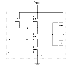
Many modern CMOS gate circuits are buffered with additional transistor stages on their outputs. For example, an unbuffered AND gate is shown here, with no more transistors than is necessary to fulfill the “AND” logic function:
One type of “buffered” CMOS AND gate looks like this:
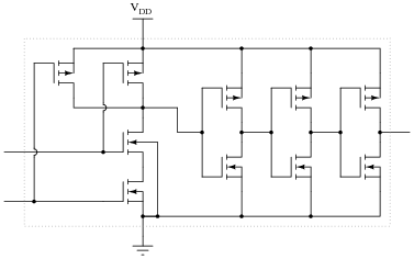
As far as the basic logic function is concerned, the additional transistors are unnecessary. However, the “buffering” they provide does serve a useful function. What is that function? Are there any disadvantages to buffered logic gates, versus unbuffered?
Reveal answerBuffered gates exhibit better noise immunity than unbuffered gates. One disadvantage to buffering, though, is increased propagation delay time.
Follow-up question: identify the on/off states of all transistors in the buffered circuit for both (high and low) input conditions.
Notes:Texas Instruments publishes an excellent application report (SCHA004 - October 2002) comparing buffered versus unbuffered CMOS logic gates. I highly recommend it for your reference.
-
Question 12 of 27
In the early days of solid-state logic gate circuit technology, there was a very clear distinction between TTL and CMOS. TTL gates were capable of switching on and off very fast, required a tightly regulated power supply voltage, and used a lot of power. CMOS gates were not quite as fast as TTL, but could tolerate a much wider range of power supply voltages and were far less wasteful on power.
Then, during the 1980’s a new technology known as high-speed CMOS, or HCMOS, entered the scene. Explain what HCMOS is, how it compares to the older TTL and CMOS families (54/74xx and 4xxx number series, respectively), and where it is often used. Hint: high-speed CMOS bears the same numerical codes as the old TTL 54xx and 74xx series ICs (e.g. 74HC00 instead of 7400).
Reveal answerI’ll let you research the answer to this question!
Notes:High-speed CMOS was a very important developmental milestone in digital logic gate technology, and it is essential for modern (2005) students of electronics to be aware of since it is so widely used. In many ways it blends the best of the old TTL and CMOS worlds, with few disadvantages.