Facebook
 Google
 GitHub
 Linkedin
Digital Circuits
Flip-Flop Circuits
26 questions By Tony R. Kuphaldt
-
Question 19 of 26
Identify at least one component fault that would cause the flip-flop to indicate “clockwise” all the time, regardless of encoder motion:
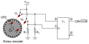
For each of your proposed faults, explain why it will cause the described problem.
Reveal answer- Phototransistor Q1 failed shorted.
- Resistor R2 failed open.
- Flipflop U1 output failed high.
Follow-up question: explain why the presence of ambient light near the phototransistors could also cause this problem to occur.
Notes:Be sure to discuss with your students the reasons why their proposed faults would cause the stated problem.
-
Question 20 of 26
Suppose a student wants to build a sound-controlled lamp control circuit, whereby a single clap or other loud burst of noise turns the lamp on, and another single clap turns it off. The sound-detection and lamp-drive circuitry is shown here:

Add a J-K flip-flop to this schematic diagram to implement the toggling function.
Reveal answer
Notes:Some students may ask whether there is any significance to using the [Q] output rather than the Q. Discuss this with your students: whether they think it will make any difference, or if it was just an arbitrary choice made by the circuit’s designer. Then, ask them how they would go about proving their judgment.
There are plenty of “what if” failure scenarios you could ask your students about here, challenging them to analyze this circuit with a troubleshooting perspective. If time permits, have some fun with this.
-
Question 21 of 26
If the clock frequency driving this flip-flop is 240 Hz, what is the frequency of the flip-flop’s output signals (either Q or [Q])?

Reveal answerfout = 120 Hz
Follow-up question: how could you use another flip-flop to obtain a square-wave signal of 60 Hz from this circuit?
Notes:Ask your students to think of some practical applications for this type of circuit. For those who are musically inclined, ask them what the musical relationship is between notes whose frequencies are an exact 2:1 ratio (hint: it’s the same interval as eight white keys on a piano keyboard). How could a circuit such as this possibly be used in a musical synthesizer?