Facebook
 Google
 GitHub
 Linkedin
Discrete Semiconductor Devices and Circuits
Junction field-effect transistors (JFET)
43 questions By Tony R. Kuphaldt
-
Question 37 of 43
The “transconductance” ratio (gm) of a field-effect transistor is a very important device parameter. In essence, it describes the amplifying power of the transistor. Give a mathematical definition for this parameter, and provide some typical values from transistor datasheets.
Reveal answerTransconductance is defined as the ratio between drain current and gate voltage. I’ll let you research some typical values. Here are some transistor part numbers you could research datasheets for:
- J110
- J308
- J309
- J310
- MPF 102
Challenge question: the “beta” ratio for a BJT (β) may be defined as the direct ratio of collector current to base current, or as the ratio between change in collector current and change in base current, as the following equations show.
$$\beta _{DC}=\frac{1_C}{I_B} \ \ \ \ \ \ \ \ \ (DC \ \ current \ \ gain \ \ for \ \ a \ \ BJT)$$
$$\beta _{AC}=\frac{\triangle 1_C}{\triangle I_B} \ \ \ \ \ \ \ \ \ (AC \ \ current \ \ gain \ \ for \ \ a \ \ BJT)$$
By contrast, the transconductance of a FET is always defined in terms of change, and never in terms of a direct ratio:
$$g_m=\frac{\triangle I_D}{\triangle V_G}$$
$$g_m \neq \frac{I_D}{V_G}$$
Explain why this is.
Notes:Ask your students to show you at least one datasheets for one of the listed transistors. With internet access, datasheets are extremely easy to locate. Your students will need to be able to locate component datasheets and application notes as part of their work responsibilities, so be sure they know how and where to access these valuable documents!
Discuss with your students why transconductance is measured in units of Siemens. Where else have they seen this unit of measurement? Why would it be an appropriate unit of measurement in this context?
-
Question 38 of 43
Bipolar junction transistors are definitely unidirectional (“polarized”) devices, able to handle electric currents in one particular direction through each terminal:
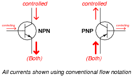
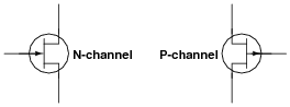
What about JFETs? Are they polarized just like BJTs? Explain your answer, complete with arrows showing proper directions of current through these two JFETs:
Reveal answer
Follow-up question: explain why there is no “controlling” current (ideally) in a JFET.
Notes:The fact that JFETs are bilateral devices rather than unilateral as bipolar junction transistors leads to some interesting applications whereby AC currents may be controlled! JFETs are often used in this capacity as AC signal switches, allowing a DC voltage to control passage or blocking of a low-amplitude AC signal such as an audio or RF signal prior to power amplification.
-
Question 39 of 43
This is a switching circuit for video signals, or any other radio-frequency (RF), low-amplitude AC signals that one might need to switch on and off for a variety of different applications:

Identify the ön” and öff” states of the three JFETs in this circuit with the switch in the position shown in the schematic, and also determine whether the switch position shown in the diagram is for “passing” or “blocking” the RF signal from input to output.
Reveal answer
With the switch in the position shown, the circuit will pass the RF signal from input to output.
Notes:Ask your students to explain the problem-solving strategy(ies) they used to derive the correct answer for this question. How were they able to tell whether the transistors would be on or off? Ask them to explain the purpose of the 1 MΩ resistors. What might happen without them?
If time permits, discuss with your students the design of this circuit: why two “pass” transistors and one “shunt” transistor? How critical is the magnitude of the -V switching control voltage?
The idea for this circuit came from a National Semiconductor application note on JFET circuits: Application Note 32, February 1970, page 13.