Facebook
 Google
 GitHub
 Linkedin
Discrete Semiconductor Devices and Circuits
Junction field-effect transistors (JFET)
43 questions By Tony R. Kuphaldt
-
Question 28 of 43
What is the proper unit of measurement for the transconductance of a field-effect transistor (or an electron tube, which exhibits similar characteristics)? Explain why this unit makes sense, based on the mathematical definition of transconductance.
Reveal answerTransconductance is measured in Siemens or mhos, the former unit being the official metric designation, and that latter being an older designation.
Notes:Although the physical meaning of transconductance (gm) is significantly different from the physical meaning of conductance (G), they share the same unit of measurement due to their respective mathematical definitions. Discuss the concept of dimensional analysis with your students if they have not yet been exposed to it thus far through their use of physics formulae.
-
Question 29 of 43
Although field-effect transistors are not usually characterized in terms of current gain as bipolar junction transistors are, it would not be wrong to speak of FETs as having current gains. Compared to a BJT, how does the current gain of a FET compare? Explain your answer.
Reveal answerField-effect transistors have enormous current gains compared to bipolar junction transistors, due to their extremely high input impedances.
Notes:Ask your students to explain why a FET (JFET or MOSFET) has such a large current gain compared to a typical BJT. What is it about the function of a field-effect transistor that makes it such a powerful current-amplifying device?
-
Question 30 of 43
Explain the operation of this JFET audio signal switch circuit:
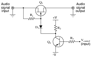
What sort of signal is necessary at pin Vcontrol to allow the audio signal to pass through the JFET, and what sort of signal turns the JFET off? Also, explain the purpose of each of these components in the audio switching circuit:
- Diode D1
- Resistor R1
- Resistor R2
- Resistor R3
Challenge question: what is the greatest peak audio signal voltage that this circuit will tolerate before misbehaving, in relation to the positive and negative DC supply voltages ( V and -V)?
Reveal answerDiode D1 prevents resistor R2 from loading the audio signal source, and resistor R1 provides a condition of VGS = 0 volts whenever transistor Q2 is in a state of cutoff. I’ll let you determine the proper Vcontrol voltage levels for “on” and “off” control states.
Notes:This circuit was taken from the February 2004 edition of Electronics World magazine, in an article written by Douglas Self. The article’s original circuit showed component values, but I show it here in generic form, and somewhat rearranged.