Facebook
 Google
 GitHub
 Linkedin
Discrete Semiconductor Devices and Circuits
Junction field-effect transistors (JFET)
43 questions By Tony R. Kuphaldt
-
Question 40 of 43
This is a switching circuit for video signals, or any other radio-frequency (RF), low-amplitude AC signals that one might need to switch on and off for a variety of different applications:

Identify the “on” and “off” states of the three JFETs in this circuit with the switch in the position shown in the schematic, and also determine whether the switch position shown in the diagram is for “passing” or “blocking” the RF signal from input to output.
Reveal answer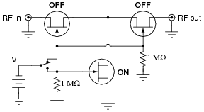
With the switch in the position shown, the circuit will block the RF signal from getting to the output.
Notes:Ask your students to explain the problem-solving strategy(ies) they used to derive the correct answer for this question. How were they able to tell whether the transistors would be on or off? Ask them to explain the purpose of the 1 MΩ resistors. What might happen without them?
If time permits, discuss with your students the design of this circuit: why two “pass” transistors and one “shunt” transistor? How critical is the magnitude of the -V switching control voltage?
The idea for this circuit came from a National Semiconductor application note on JFET circuits: Application Note 32, February 1970, page 13.
-
Question 41 of 43
A very simple circuit that may be used as a current regulator in a DC circuit is this:
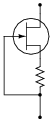
Draw a battery symbol and any necessary connecting wires to form a complete DC current source, that will attempt to supply a regulated amount of DC current through any given load.
Reveal answer
Notes:The direction of current through the JFET, when used as a current regulator in this fashion, is very important. Not so much for the JFET’s sake, as for the sake of establishing the correct type of feedback (negative) to make the circuit self-regulating.
Discuss this circuit’s operation with your students, asking them to determine the polarity of the resistor’s voltage drop, and how that relates to the “pinching off” of the JFET.
-
Question 42 of 43
The following circuit is useful as a current regulator, the regulated current setpoint being established by the value of the resistor and the JFET’s VGS(off) parameter:

Despite wide variations in VDD, the current in this circuit will remain relatively constant. The reason this circuit works as it does is negative feedback. Explain what causes negative feedback to occur in this circuit, and why it has a stabilizing effect on the current.
Reveal answerThe resistor creates a voltage drop that tries to pinch off the JFET as current increases. To put it in colloquial terms, “when the current zigs, the JFET zags.”
Notes:This is a simple example of negative feedback in action: one that does not require any AC analysis and all its associated considerations. Here it is just DC at work, and the students must determine what it is the JFET/resistor combination does in response to attempted changes in current that makes the current so stable.