Facebook
 Google
 GitHub
 Linkedin
Discrete Semiconductor Devices and Circuits
Regulated Power Sources
28 questions By Tony R. Kuphaldt
-
Question 7 of 28
Describe what happens to the collector current of the transistor as the variable resistor’s value is changed:
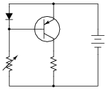
Hint: it is helpful to remember that the voltage drop across a PN junction is not exactly constant as the current through it varies. There is a nonlinear relationship between diode voltage drop (VD) and diode current (ID) as described by the diode equation:
$$I_D= I_S(e^{(\frac{qV_D}{NkT})} -1)$$ Reveal answerThe transistor’s collector current rises and falls with the diode’s current, as dictated by the variable resistor. Ideally, the transistor collector current precisely matches the diode’s current.
Notes:This circuit is really the beginning of a current mirror. I have found this to be an excellent starting point for student learning on linear transistor operation, as well as a good practical introduction of current regulation circuits. Once students recognize that bipolar transistors are essentially voltage-controlled current regulators (albeit very nonlinear!), they are ready to comprehend their application as signal amplifiers.
-
Question 8 of 28
The circuit shown here is a simple current mirror. Explain what happens as the load resistance changes:
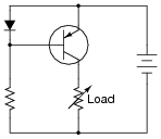
Most current mirrors are not built exactly like this. Instead of a diode, they use a transistor (identical to the other transistor) with the base and collector terminals shorted together:
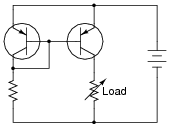
Ideally, the two transistors are built on the same substrate material, so as to always be at equal temperature. Explain why this design is preferable to the first circuit (using the diode) shown in this question.
Reveal answerAs the load resistance changes, the current through it remains approximately the same. In the first current mirror circuit where a transistor receives its controlling signal from a diode (rather than another transistor), there is a tendency for the transistor to thermally “run away,” allowing more and more current through the load over time.
Follow-up question: explain how to adjust the regulated current’s target value in either of these circuits.
Notes:Current mirrors confuse beginning students primarily because they cannot be understood following the simplistic model of a silicon PN junction always dropping 0.7 volts. Rather, their operation is inextricably connected with Shockley’s diode equation. This question is therefore not only a good review of that equation, but it also illustrates how the “models” we use to explain things are sometimes shown to be inadequate.
-
Question 9 of 28
Two terms used commonly in electronics are sourcing and sinking, in reference to the direction of electric current between an active circuit and a load:
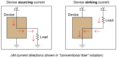
A practical example of where this distinction is important is in certain integrated circuits (IC “chips”) where output pins may be able to only sink current, only source current, or both sink and source current.. Take a look at these two examples, each where an integrated circuit “chip” controls power to an LED. In one instance the IC is wired to source current to the LED, and in the other instance it is wired to sink current from the LED:
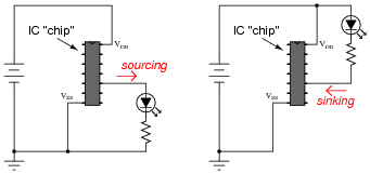
If an IC is only able to do one or the other (source or sink current, but not both), it makes a big difference how you connect load devices to it! What makes the difference between a circuit that is able to source current versus a circuit that is able to sink current is the internal configuration of its transistors.
Similarly, a current mirror circuit may be built to either source current or sink current, but not do both. Draw current mirror circuits within the dotted-line boxes suitable for sourcing and sinking current to a load resistor:
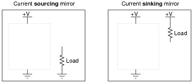
Reveal answer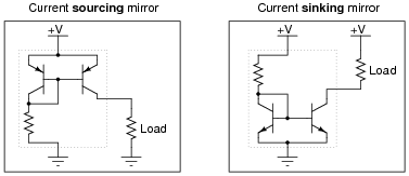
Notes:This question challenges students’ ability to “manipulate” the basic current mirror circuit into two different configurations. Depending on how well your students grasp the basic concept, you might want to spend extra discussion time comparing the two circuits, tracing current through each and discussing their operation in general.
Although it may seem trivial to an experienced instructor or electronics professional, variations of circuit designs consisting solely of inverting components are often quite confusing to students, especially those weak in spatial-relations skills. I encourage you to work with those students regularly to build this important visualization skill.