Facebook
 Google
 GitHub
 Linkedin
Discrete Semiconductor Devices and Circuits
Regulated Power Sources
28 questions By Tony R. Kuphaldt
-
Question 22 of 28
A very useful feature for a regulated voltage source is an electronic current limit: a circuit that limits the amount of current deliverable to a load, so as to avoid needless fuse-blowing. The combination of transistor Q2 and resistor R2 provides just this feature for the following voltage regulator circuit:
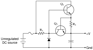
Describe how transistor Q2 limits the current sourced to a direct short-circuit across the load terminals.
Reveal answerTransistor Q2 turns on in the event that excessive current goes through the load, effectively connecting the zener diode’s cathode to the V output terminal, which decreases the regulation setpoint voltage until the load current diminishes to an acceptable level.
Follow-up question: what component value(s) would we have to change in order to adjust the current limit in this power supply circuit?
Notes:Ask your students to identify what it is that turns transistor Q2 on.
If students have difficulty understanding the limiting function of transistor Q2, just tell them to replace Q2 with a direct short (between the collector and emitter terminals of Q2), and re-analyze the circuit. They should see that transistor Q1 is unable to turn on in this condition.
A very helpful strategy in analyzing what happens in an electronic circuit as variables change is to imagine those variables assuming extreme states. In this case, to see the trend that occurs when Q2 starts to conduct, imagine Q2 conducting perfectly (a short between collector and emitter). Conversely, if we wanted to see what the circuit would do under conditions where Q2 is in cutoff mode, just replace Q2 with an open-circuit. While not always reliable, this technique often helps to overcome mental obstacles in analysis, and is a skill you should encourage in your students’ discussion sessions often.
-
Question 23 of 28
Suppose you had the boring job of manually maintaining the output voltage of a DC generator constant. Your one and only control over voltage is the setting of a rheostat:
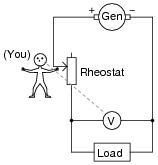
What would you have to do to maintain the load voltage constant if the load resistance changed so as to draw more current? Being that your only control over load voltage is the adjustment of a variable resistance in series with the generator, what does this imply about the generator’s output voltage (directly across the generator terminals), compared to the target load voltage?
Reveal answerIn order to increase the load voltage, you must decrease the resistance of the rheostat. In order for this scheme to work, the generator’s voltage must be greater than the target load voltage.
Note: this general voltage control scheme is known as series regulation, where a series resistance is varied to control voltage to a load.
Notes:The direction of rheostat adjustment should be obvious, as is the fact that the generator’s voltage must be at least as high as the intended (target) load voltage. However, it may not be obvious to all that the generator’s voltage cannot merely be equal to the intended load voltage.
To illustrate the necessity of this, ask your students how the system would work if the generator’s output voltage was exactly equal to the intended load voltage. Emphasize the fact that the generator is not perfect: it has its own internal resistance, the value of which cannot be changed by you. What position would the rheostat have to be in, under these conditions, in order to maintain target voltage at the load? Could the target voltage be maintained at all?
-
Question 24 of 28
Suppose you had the boring job of manually maintaining the output voltage of a DC generator constant. Your one and only control over voltage is the setting of a rheostat:
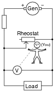
What would you have to do to maintain the load voltage constant if the load resistance changed so as to draw more current? Being that your only control over load voltage is the adjustment of a variable resistance in parallel with the load, what does this imply about the generator’s output voltage (directly across the generator terminals), compared to the target load voltage?
Reveal answerIn order to increase the load voltage, you must increase the resistance of the rheostat. In order for this scheme to work, the generator’s voltage must be greater than the target load voltage.
Note: this general voltage control scheme is known as shunt regulation, where a parallel (shunt) resistance is varied to control voltage to a load.
Follow-up question: assuming the load voltage is maintained at a constant value by an astute rheostat operator despite fluctuations in load current, how would you characterize the current through the generator’s windings? Does it increase with load current, decrease with load current, or remain the same? Why?
Notes:The direction of rheostat adjustment should be obvious, as is the fact that the generator’s voltage must be at least as high as the intended (target) load voltage. However, it may not be obvious to all that the generator’s voltage cannot merely be equal to the intended load voltage.
To illustrate the necessity of this, ask your students how the system would work if the generator’s output voltage was exactly equal to the intended load voltage. Emphasize the fact that the generator is not perfect: it has its own internal resistance, the value of which cannot be changed by you. What position would the rheostat have to be in, under these conditions, in order to maintain target voltage at the load? Could the target voltage be maintained at all?
A helpful analogy for students is that of a car with an automatic transmission, with its speed being controlled by the brake pedal while the accelerator pedal is maintained at a constant position. This is not the most energy-efficient method of speed control, but it will work within certain limits!