Facebook
 Google
 GitHub
 Linkedin
Discrete Semiconductor Devices and Circuits
Regulated Power Sources
28 questions By Tony R. Kuphaldt
-
Question 16 of 28
Calculate the approximate output voltage of this regulated power supply circuit and the amount of current through the zener diode under no-load conditions:

Reveal answerVout ≈ -8.6 V Izener ≈ 6.71 mA
Notes:Calculating the output voltage is a much simpler task than calculating the zener diode’s current! Have your students explain their problem-solving techniques for this circuit.
-
Question 17 of 28
Calculate the approximate output voltage of this regulated power supply circuit, the amount of current through the zener diode, and the (unregulated) voltage across the 1000 μF capacitor, all under no-load conditions:
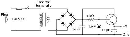
Reveal answerVout ≈ 6.2 V Izener ≈ 25.6 mA Vcapacitor = 32.5 V
Notes:Calculating the output voltage is a much simpler task than calculating the zener diode’s current! Have your students explain their problem-solving techniques for this circuit.
-
Question 18 of 28
Predict how all component voltages and currents in this circuit will be affected as a result of the following faults. Consider each fault independently (i.e. one at a time, no multiple faults):

- Resistor R1 fails open:
- Transistor Q1 fails open, collector to emitter:
- Transistor Q1 fails shorted, collector to emitter:
- Transistor Q2 fails open, collector to emitter:
- Transistor Q2 fails shorted, collector to emitter:
- Load fails shorted:
For each of these conditions, explain why the resulting effects will occur.
Reveal answer- Resistor R1 fails open: No current through Q1, no current through Q2, no current through load, no voltage dropped across Q1, full voltage dropped across collector-emitter of Q2.
- Transistor Q1 fails open, collector to emitter: Approximately the same current through R1, increased current through Q2 base, increased current through Q2 collector (load current),and less voltage dropped between collector-emitter of Q2.
- Transistor Q1 fails shorted, collector to emitter: Increased current through R1, almost zero current through all terminals of Q2 and the load, full voltage dropped across collector-emitter of Q2.
- Transistor Q2 fails open, collector to emitter: No change in current for R1 or Q1, zero load current, full voltage dropped across collector-emitter of Q2.
- Transistor Q2 fails shorted, collector to emitter: Current through R1 will most likely increase, zero voltage dropped across collector-emitter of Q2, increased current through Q2 and load.
- Load fails shorted: No change in any current (in reality, load current will slightly increase), increased voltage drop across collector-emitter of Q2, possible overheating of Q2.
Notes:The purpose of this question is to approach the domain of circuit troubleshooting from a perspective of knowing what the fault is, rather than only knowing what the symptoms are. Although this is not necessarily a realistic perspective, it helps students build the foundational knowledge necessary to diagnose a faulted circuit from empirical data. Questions such as this should be followed (eventually) by other questions asking students to identify likely faults based on measurements.