Facebook
 Google
 GitHub
 Linkedin
Discrete Semiconductor Devices and Circuits
Regulated Power Sources
28 questions By Tony R. Kuphaldt
-
Question 19 of 28
Predict how this power supply circuit’s output voltage will be affected as a result of the following faults. Also note whether or not any other components in this circuit will become stressed as a result of each fault. Consider each fault independently (i.e. one at a time, no multiple faults):

- Transformer T1 primary winding fails shorted:
- Transformer T1 secondary winding fails open:
- Rectifying diode D3 fails open:
- Zener diode D5 fails open:
- Zener diode D5 fails shorted:
- Resistor R1 fails open:
- Capacitor C2 fails shorted:
For each of these conditions, explain why the resulting effects will occur.
Reveal answer- Transformer T1 primary winding fails shorted: Fuse immediately blows, then output voltage falls to zero (after filter capacitors have discharged).
- Transformer T1 secondary winding fails open: Output voltage falls to zero (after filter capacitors C1 and C2 have discharged).
- Rectifying diode D3 fails open: No change in output voltage (except when heavily loaded, where there will be increased ripple voltage).
- Zener diode D5 fails open: Output voltage rises to approximately same level as unregulated voltage (across capacitor C1).
- Zener diode D5 fails shorted: Output voltage falls to zero (as quickly as C2 can discharge), resistor R1 may overheat.
- Resistor R1 fails open: Output voltage falls to zero (as quickly as C2 can discharge).
- Capacitor C2 fails shorted: Output voltage falls to a very low value, transistor Q1 will most likely overheat.
Notes:The purpose of this question is to approach the domain of circuit troubleshooting from a perspective of knowing what the fault is, rather than only knowing what the symptoms are. Although this is not necessarily a realistic perspective, it helps students build the foundational knowledge necessary to diagnose a faulted circuit from empirical data. Questions such as this should be followed (eventually) by other questions asking students to identify likely faults based on measurements.
-
Question 20 of 28
Suppose this regulated power supply circuit used to function fine, but now has stopped outputting any DC voltage at all:
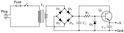
Initial diagnostic measurements show there to be full DC (unregulated) voltage across capacitor C1, and no DC voltage between the transistor base and ground. From this data, where would you suspect the problem is?
Reveal answerMost likely R1 failed open or the zener diode D5 failed shorted, such that the transistor is not being “told” to output any voltage at its emitter terminal.
Notes:Ask your students why the diagnostic measurements described in the question are good points to check (in the order that they were taken).
-
Question 21 of 28
Many different types of sensors work on the principle of a variable resistance representing a different physical quantity. One such sensor is the common fuel level sensor used in automotive, marine, and industrial fuel storage applications:
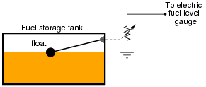
As the fuel level in the tank changes, the float position will change, changing the sensor’s resistance. This resistance change is detected by an electric gauge (a special type of meter), which then provides visual indication of fuel level in the tank.
We must have some accurate way of measuring electrical resistance in order for this scheme to work. One common technique for doing this is to pass a constant current through the sensor resistance and then measure the voltage dropped across it. Since current mirror circuits function as current regulators, and therefore may be used as current sources if supplied with an external voltage, we could use a current mirror to force constant current through the fuel level sensor:
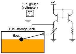
One problem with the circuit shown is that the sensor current will change as the supply voltage ( V) changes. This may be important to us, because the DC system voltage on an automobile may not be very stable, and this could lead to inaccuracies in fuel level measurement.
Figure out a way we could use a zener diode to stabilize the voltage in this current mirror circuit so that supply voltage changes would have minimal effect on the amount of current through the variable-resistance sensor.
Reveal answer
Notes:Students may try to implement a voltage regulation system for the entire circuit, sensor and everything, but this is unnecessary. Using a zener diode to regulate voltage for the right-hand portion of the current mirror circuit so that the right-hand transistor (acting as diode) receives constant current is all that is necessary. The left-hand transistor should faithfully regulate current through the sensor despite changes in sensor resistance and changes in supply voltage.