Facebook
 Google
 GitHub
 Linkedin
Discrete Semiconductor Devices and Circuits
Regulated Power Sources
28 questions By Tony R. Kuphaldt
-
Question 13 of 28
Choose a power supply voltage and resistance value for R1 that will maintain approximately 15 mA of current through the 1 kΩ load resistor. Assume the use of a silicon transistor:
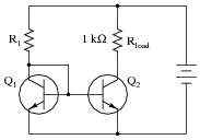
To ensure plenty of regulation range (the ability to maintain regulated current over a wide range of load resistance values), design your circuit so that at least 20 volts VCE are dropped across transistor Q2. Also, calculate the approximate power dissipation of transistor Q2.
Reveal answerNote that this is just one possible set of values meeting the criteria given for this circuit. Your own answers may be different!
R1 = 2.287 kΩ Vsupply = 35 volts PQ2 ≈ 300 mW
Notes:Since there is more than one current answer for this design problem, be sure to ask students to present different solutions to it, asking them to explain how they obtained their answers to this question.
-
Question 14 of 28
Describe the purpose of the transistor in this AC-DC power supply circuit:
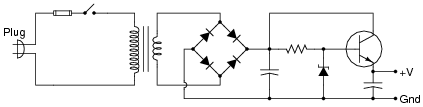
Reveal answerThe transistor serves to “boost” the current-sourcing capability of the resistor/zener voltage regulator circuit, to provide far more current to a load than possible with the resistor/zener alone.
Notes:Ask your students to identify the configuration of this transistor amplifier (common-base, common-emitter, or common collector?). After they have done this, ask them to identify the current gain of such an amplifier, given a transistor β value of 90.
-
Question 15 of 28
Install a potentiometer in this circuit so that the regulated output voltage of this power supply becomes adjustable:
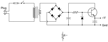
Challenge: leave the potentiometer symbol in its place, and make the necessary wire connections between it and the rest of the circuit!
Reveal answer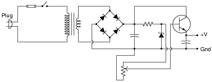
Challenge question: for any given amount of load current, what voltage setting will cause the transistor to dissipate the most heat energy, low, medium, or high?
Notes:Some students may choose to place the potentiometer on the output of the power supply (connecting to the transistor’s emitter terminal). While this will work, technically, it is not a good solution because the load current will be severely limited by the potentiometer’s resistance. Discuss with your students why the circuit drawn in the answer is more practical.
The answer to the challenge question is nonintuitive, but it makes sense once you determine what variables affect transistor power dissipation (emitter current, and VCE).