
 Facebook
 Google
 GitHub
 Linkedin
AC Electric Circuits
Step-up, Step-down, and Isolation Transformers
34 questions By Tony R. Kuphaldt
-
Question 31 of 34
Suppose a step-down transformer fails due to an accidental short-circuit on the secondary (load) side of the circuit:

That the transformer actually failed as a result of the short is without any doubt: smoke was seen coming from it, shortly before current in the circuit stopped. A technician removes the burned-up transformer and does a quick continuity check of both windings to verify that it has failed open. What she finds is that the primary winding is open but that the secondary winding is still continuous. Puzzled at this finding, she asks you to explain how the primary winding could have failed open while the secondary winding is still intact, if indeed the short occurred on the secondary side of the circuit. What would you say? How is it possible that a fault on one side of the transformer caused the other side to be damaged?
Reveal answerA short-circuit would cause current in both windings of the transformer to increase.
Notes:It is important for students to realize that a transformer “reflects” load conditions on the secondary side to the primary side, so that the source “feels” the load in all respects. What happens on the secondary (load) side will indeed be reflected on the primary (source) side.
-
Question 32 of 34
An AC motor receives reduced voltage through a step-down transformer so it may properly operate on a 277 volt source:

After years of trouble-free operation, something fails. Now, the motor refuses to operate when both switches are closed. A technician takes four voltage measurements between the following test points with both switches in the “on” position:
Step Measurement
1 VTP2−Gnd = 277 V
2 VTP3−Gnd = 277 V
3 VTP5−Gnd = 0 V
4 VTP4−Gnd = 0 V
Complete this expanded table, following the technician’s steps in the same order as the voltage measurements were taken, labeling each component’s status as either “O” (possibly open), “S” (possibly shorted), or “OK” (known to be good). The first row of the table should contain many possible fault labels (because with little data there are many possibilities), but as more measurements are taken you should be able to limit the possibilities. Assume that only one component is faulted.
Step Measurement SW1 Fuse Primary Secondary SW2 Motor
1 VTP2−Gnd = 277 V
2 VTP3−Gnd = 277 V
3 VTP5−Gnd = 0 V
4 VTP4−Gnd = 0 V
Reveal answer
Step Measurement SW1 Fuse Primary Secondary SW2 Motor
1 VTP2−Gnd = 277 V OK O O O O O
2 VTP3−Gnd = 277 V OK OK O O O O
3 VTP5−Gnd = 0 V OK OK O O O OK
4 VTP4−Gnd = 0 V OK OK O O OK OK
Either the primary or the secondary winding is failed open!Follow-up question: describe what you would measure next in this circuit to determine whether it is the primary or secondary winding that has failed open.
Notes:Students may ask why it is possible for us to say that the second switch and motor are okay after the technician measured 0 volts before each. Certainly we know something has failed before the points where 0 volts is measured, but that does not tell us the health of components after those points! The answer to this very good question is the assumption stated at the end of the question: that we are to assume only one component fault in the circuit. If either switch 2 or the motor were failed open, it would still not account for a lack of voltage between TP4 and ground. A shorted motor might, but then the fuse would have blown, resulting in 0 volts between TP3 and ground. So, we assume the motor and switch 2 must be okay because only some other single fault could cause the measurements we are reading.
-
Question 33 of 34
Ethernet is a popular communications standard for many digital devices, personal computers included. Originally, Ethernet was intended to be a network standard for conveying digital data only, without power. In later years, however, upgrades to the standard allowed DC power to be conveyed over the same wire pairs. The IEEE standard 802.3af is one example of a power-over-Ethernet standard.
Shown here is a schematic showing how two Ethernet devices connect together over a Category 5 (“Cat 5”) twisted-pair cable, with no DC power conveyed over the cabling:
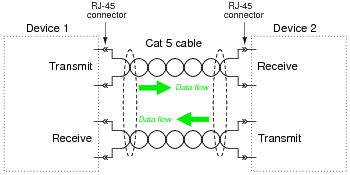
Digital data consists of voltage pulses over time (AC, essentially), conducted between the two devices over two sets of twisted-pair wires.
The next schematic shows the 802.3af standard allowing both DC power and digital data to be communicated over the same pairs of wires. Note the use of transformers at each device:
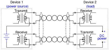
Explain what function(s) the transformers provide in this system, and how they allow DC power to travel through the wire pairs from source to load without interfering with the Ethernet data signals, which are AC.
Reveal answerTrace the DC current from source to load and you will see that there is zero net magnetic flux in the transformer cores resulting from the DC, meaning that the transformers do not “see” the DC current for all practical purposes.
Notes:This is an interesting application of transformers: isolation of DC allowing a form of “power line carrier” system to be made without the use of filter networks.
Actually, there is more to the 802.3af standard than what is shown in the second schematic diagram. This standard also allows the use of the other two pairs of wires in Cat 5 cable as dedicated power conductors. I omit this aspect for simplicity.





Creative and interesting excercises.