
 Facebook
 Google
 GitHub
 Linkedin
AC Electric Circuits
Step-up, Step-down, and Isolation Transformers
34 questions By Tony R. Kuphaldt
-
Question 10 of 34
Shown here is a schematic diagram of a transformer powering a resistive load, at the exact moment in time where the primary winding’s voltage is at its positive ( ) peak:

Identify the polarity of voltage across the load resistor at this exact moment in time, as well as the direction of current in each of the windings.
Reveal answer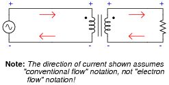
Follow-up question: note the relationship between direction of current and polarity of voltage for each of the transformer windings. What do these different relationships suggest, in regard to the “flow” of power in the circuit?
Notes:One perspective that may help students understand the directions of current through each winding of the transformer, in relation to the voltage polarities, is to think of each winding as either being a source of electrical power or a load. Ask your students, “which winding acts as a source in this circuit, and which one acts as a load? Imagine these sources and loads are DC (so we may maintain the same polarity of voltage, for the sake of analysis). Which way would you draw the currents for a DC source and for a DC load?
-
Question 11 of 34
The ignition coil of a gasoline-powered internal combustion automobile engine is an example of a transformer, although it is not powered by alternating current. Explain how a transformer may be operated on electricity that is not AC:
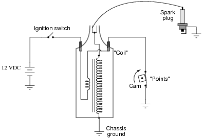
Reveal answerIn order for a transformer to function, the primary winding current must change rapidly with regard to time. Whether this is a current that truly alternates, or just one that pulses in the same direction, is irrelevant.
Challenge question: is the wave-shape of the secondary voltage sinusoidal? Why or why not?
Notes:This is a very common application of transformer technology: the ignition “coil” used to ignite the air-fuel mixture inside a gasoline engine’s combustion chamber. This question also addresses an issue sometimes misunderstood by students, that transformers are fundamentally AC devices, not DC.
It might be a good idea to have an automotive ignition coil available for for classroom demonstration. In lieu of a spark plug, a neon lamp may be used to indicate the presence of high voltage.
As for answering the challenge question, an oscilloscope will quickly prove the nature of the waveshape, for any transformer energized with pulsating DC.
-
Question 12 of 34
Something has failed in this circuit, because the light bulb does not light up when the switch is closed:
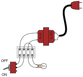
What type(s) of transformer fault(s) would cause a problem like this, and how might you verify using a multimeter?
Reveal answerThe most common type of transformer fault causing a problem like this is an open winding. This is very easy to check using a multimeter (I’ll let you answer this part of the question!).
Notes:Of course, faults in this circuit having nothing to do with the transformer could also prevent the light bulb from lighting. If time permits, it would be good to analyze a few failure scenarios with your students, challenging them to locate the source of the trouble as efficiently as possible.





Creative and interesting excercises.