
 Facebook
 Google
 GitHub
 Linkedin
AC Electric Circuits
Step-up, Step-down, and Isolation Transformers
34 questions By Tony R. Kuphaldt
-
Question 7 of 34
Calculate the source current and load current in this transformer circuit:

Isource = Iload =
Reveal answerIsource = 187.5 mA Iload = 72.73 mA
Notes:Most transformer problems are nothing more than ratios, but some students find ratios difficult to handle. Questions such as this are great for having students come up to the board in the front of the classroom and demonstrating how they obtained the results.
-
Question 8 of 34
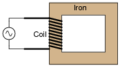
If a coil of insulated wire is wrapped around an iron core, an inductance will be formed. Even if the wire has negligible resistance, the current through the coil from an AC source will be limited by the inductive reactance (XL) of the coil, as the magnetic flux in the iron core oscillates back and forth to induce a counter-EMF:
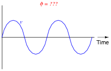
Plot the instantaneous magnetic flux (φ) waveform in the iron core corresponding to the instantaneous applied voltage (v) shown in this graph:
Reveal answer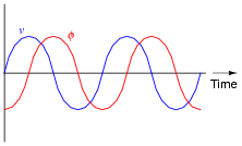
Notes:There is a simple formula (albeit containing a derivative term) describing the relationship between instantaneous flux (φ) and instantaneous induced voltage (v). Your students ought to know what it is, and that it should be applied to this question!
-
Question 9 of 34
If we energize an inductor’s coil with an oscillating (AC) voltage, we will generate an oscillating magnetic flux in the inductor core:
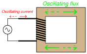
If we wrap a second coil of wire around the same magnetic core as the first (inductor) coil, we set up a situation where mutual inductance exists: a change of current through one coil induces a voltage in the other, and visa-versa. This, obviously, will result in an AC voltage being induced in the second wire coil:
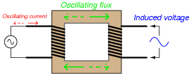
What name is given to such a device, with two coils of wire sharing a common magnetic flux? Also, plot both the magnetic flux waveform and the secondary (induced) voltage waveform on the same graph as the primary (applied) voltage waveform:
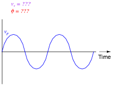
Reveal answerThis device is called a transformer.
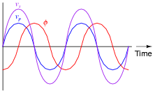
Note: the relative amplitudes of vp and vs are arbitrary. I drew them at different amplitudes for the benefit of the reader: so the two waveforms would not perfectly overlap and become indistinguishable from one another.
Notes:Ask your students how the secondary coil would have to be made in order to truly generate a voltage greater than the applied (primary) coil voltage. How about generating a secondary voltage less than the primary?




Creative and interesting excercises.