Facebook
 Google
 GitHub
 Linkedin
Digital Circuits
Counters
34 questions By Tony R. Kuphaldt
-
Question 28 of 34
A technician is trying to build a timer project using a set of cascaded counters, each one connected to its own 7-segment decoder and display:
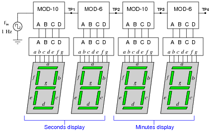
The technician was trying to troubleshoot this circuit, but left without finishing the job. You were sent to finish the work, having only been told that the timer circuit “has some sort of problem.” Your first step is to start the 1 Hz clock and watch the timing sequence, and after a few minutes of time you fail to notice anything out of the ordinary.
Now, you could sit there for a whole hour and watch the count sequence, but that might take a long time before anything unusual appears for you to see. Devise a test procedure that will allow you to pinpoint problems at a much faster rate.
Reveal answerDisconnect the 1 Hz clock pulse generator and re-connect the counter input to a square-wave signal generator of variable frequency. This will speed up the counting sequence and allow you to see what the problem is much faster!
Follow-up question: suppose you did this and found no problem at all. What would you suspect next as a possible source of trouble that could cause the timer circuit to time incorrectly?
Notes:Connecting a faulty circuit to a different input signal than what it normally runs at is an excellent way to explore faults. However, it should be noted that some faults may go undetected using this technique, because you have altered the circuit in the process.
-
Question 29 of 34
Explain the difference between a synchronous counter and an asynchronous counter circuit.
Reveal answerA “synchronous” counter circuit’s flip-flops are clocked simultaneously, while each of the “asynchronous” counter circuit’s flip-flops is clocked by the output of the preceding flip-flop.
Notes:Ask your students to discuss what advantages, if any, one of these counter circuit types may have over the other.
-
Question 30 of 34
Draw the schematic diagram for a four-bit binary “up” counter circuit, using J-K flip-flops.
Reveal answerThe circuit shown here is not the only valid solution!

Follow-up question: what other configuration of J-K flip-flops could be used to make a four bit binary “up” counter?
Notes:Be sure to discuss the follow-up question with your students. It is important that they understand how to make both “up” and “down” counters using J-K flip-flops, and that there are two basic methods to make each direction of counter.