Facebook
 Google
 GitHub
 Linkedin
Digital Circuits
Counters
34 questions By Tony R. Kuphaldt
-
Question 4 of 34
Counter circuits built by cascading the output of one flip-flop to the clock input of the next flip-flop are generally referred to as ripple counters. Explain why this is so. What happens in such a circuit that earns it the label of “ripple”? Is this effect potentially troublesome in circuit operation, or is it something of little or no consequence?
Reveal answerWhen these counters increment or decrement, they do so in such a way that the respective output bits change state in rapid sequence (“rippling”) rather than all at the same time. This creates false count outputs for very brief moments of time.
Whether or not this constitutes a problem in a digital circuit depends on the circuit’s tolerance of false counts. In many circuits, there are ways to avoid this problem without resorting to a re-design of the counter.
Notes:If your students have studied binary adder circuits, they should recognize the term “ripple” in a slightly different context. Different circuit, same problem.
-
Question 5 of 34
A style of counter circuit that completely circumvents the “ripple” effect is called the synchronous counter:

Complete a timing diagram for this circuit, and explain why this design of counter does not exhibit “ripple” on its output lines:

Challenge question: to really understand this type of counter circuit well, include propagation delays in your timing diagram.
Reveal answerThe timing diagram shown here is ideal, with no propagation delays shown:
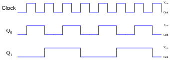
However, even with propagation delays included (equal delays for each flip-flop), you should find there is still no “ripple” effect in the output count.
Notes:“Walk” through the timing diagram given in the answer, and have students explain how the logic states correspond to a two-bit binary counting sequence.
-
Question 6 of 34
A student just learned how a two-bit synchronous binary counter works, and he is excited about building his own. He does so, and the circuit works perfectly.
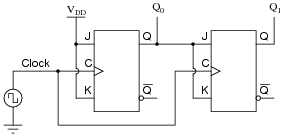
After that success, student tries to expand on their success by adding more flip-flops, following the same pattern as the two original flip-flops:

Unfortunately, this circuit didn’t work. The sequence it generates is not a binary count. Determine what the counting sequence of this circuit is, and then try to figure out what modifications would be required to make it count in a proper binary sequence.
Reveal answerThe errant count sequence is as such, with only eight unique states (there should be sixteen!): 0000, 0001, 0010, 0111, 1000, 1001, 1010, and 1111. A corrected up-counter circuit would look like this:

Notes:I like to introduce students to synchronous counter circuitry by first having them examine a circuit that doesn’t work. After seeing a two-bit synchronous counter circuit, it makes intuitive sense to most people that the same cascaded flip-flop strategy should work for synchronous counters with more bits, but it doesn’t. When students understand why the simple scheme doesn’t work, they are prepared to understand why the correct scheme does.