Facebook
 Google
 GitHub
 Linkedin
Digital Circuits
Counters
34 questions By Tony R. Kuphaldt
-
Question 13 of 34
The following circuit is known as a Johnson counter:

Describe the output of this circuit, as measured from the Q output of the far right flip-flop, assuming that all flip-flops power up in the reset condition.
Also, explain what this modified version of the above Johnson counter circuit will do, in each of the five selector switch positions:

Reveal answerJohnson counters provide a divide-by-n frequency reduction. The second counter circuit shown has the ability to select different values for n.
Notes:Strictly speaking, this circuit is a divide-by-2n counter, because the frequency division ratio is equal to twice the number of flip-flops.
The final (#5) switch position is interesting, and should be discussed among you and your students.
-
Question 14 of 34
Suppose we had two four-bit synchronous up/down counter circuits, which we wished to cascade to make one eight-bit counter. Draw the necessary connecting wires (and any extra gates) between the two four-bit counters to make this possible:

After deciding how to cascade these counters, imagine that you are in charge of building and packaging four-bit counter circuits. The customers who buy your counters might wish to cascade them as you did here, but they won’t have the ability to “go inside” the packaging as you did to connect to any of the lines between the various flip-flops. This means you will have to provide any necessary cascading lines as inputs and outputs on your pre-packaged counters. Think carefully about how you would choose to build and package your four-bit “cascadable” counters, and then draw a schematic diagram.
Reveal answerThis first solution requires some elimination of wires and one gate from the front end of the second counter . . .

. . . while this solution does only requires different AND gates (3-input instead of 2-input) on the first flip-flop stage of the second counter:

I’ll let you decide how you might wish to package your four-bit counter circuits, so as to allow easy cascading. This will be an excellent topic for classroom discussion!
Follow-up question: why isn’t the following circuit an acceptable solution?
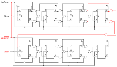
Notes:Figuring out how to cascade the two four-bit counters is the easy part. The challenge is to “think ahead” in designing a four-bit counter with all the necessary connections to make cascading easy for the end-user. Make this the center of discussion on this particular question.
-
Question 15 of 34
Here is an eight-bit counter comprised of two four-bit 74HCT163 synchronous binary counters cascaded together:
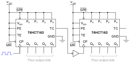
Explain how this counter circuit works, and also determine which output bit is the LSB and which is the MSB.
Now, examine this eight-bit counter comprised of the same two ICs:
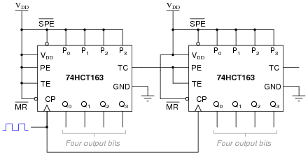
Explain how this counter circuit works, and how its operation differs from the previous eight-bit counter circuit.
Reveal answerThe first circuit shows two four-bit counters cascaded together in a ripple fashion. The second circuit shows the same two four-bit counters cascaded in a synchronous fashion. In both cases, Q0 of the left counter is the LSB and Q3 of the right counter is the MSB.
Follow-up question: comment on which method of cascading is preferred for this type of counter IC. Is the functional difference between the two circuits significant enough to warrant concern?
Notes:It is important for students to consult the datasheet for the 74HCT163 counter circuit in order to fully understand what is going on in these two cascaded counter circuits.