Facebook
 Google
 GitHub
 Linkedin
Digital Circuits
Counters
34 questions By Tony R. Kuphaldt
-
Question 25 of 34
The following RC circuit constitutes an automatic reset network for the counter. At power-up, it resets the counter to 0000, then allows it to count normally:

Predict how the operation of this automatic reset circuit will be affected as a result of the following faults. Consider each fault independently (i.e. one at a time, no multiple faults):
- Resistor R1 fails open:
- Resistor R2 fails open:
- Resistor R3 fails open:
- Capacitor C1 fails shorted:
For each of these conditions, explain why the resulting effects will occur.
Reveal answer- Resistor R1 fails open: Counter may not reset at power-up.
- Resistor R2 fails open: Counter will not count, output stuck at 0000.
- Resistor R3 fails open: Counter will not count, output stuck at 0000.
- Capacitor C1 fails shorted: Counter will not count, output stuck at 0000.
Follow-up question: suggest some reasonable values for the three resistors and the capacitor.
Notes:The purpose of this question is to approach the domain of circuit troubleshooting from a perspective of knowing what the fault is, rather than only knowing what the symptoms are. Although this is not necessarily a realistic perspective, it helps students build the foundational knowledge necessary to diagnose a faulted circuit from empirical data. Questions such as this should be followed (eventually) by other questions asking students to identify likely faults based on measurements.
-
Question 26 of 34
A student is trying to get a 74HC192 up/down counter to function. However, it is simply not cooperating:

Determine what the student is doing wrong with this 74HC192, and then correct the schematic diagram.
Reveal answerDid you think I was just going to give the answer away here? Consult a datasheet for the 74HC192 to see for yourself!
Notes:The point of this question is to have students research a datasheet to figure out the necessary conditions for making a digital IC perform as it should. This is extremely important for students to get into the habit of doing, as it will save them much trouble as technicians!
-
Question 27 of 34
This Johnson counter circuit is special. It outputs three square-wave signals, shifted 120o from one another:
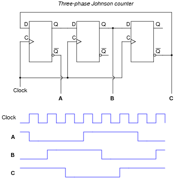
Suppose the middle flip-flop’s Q output fails in the “high” state. Plot the new output waveforms for signals A, B, and C. Assume all Q outputs begin in the “low” state (except for the middle flip-flop, of course):
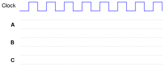
Reveal answer
Notes:The purpose of this question is to approach the domain of circuit troubleshooting from a perspective of knowing what the fault is, rather than only knowing what the symptoms are. Although this is not necessarily a realistic perspective, it helps students build the foundational knowledge necessary to diagnose a faulted circuit from empirical data. Questions such as this should be followed (eventually) by other questions asking students to identify likely faults based on measurements.