Facebook
 Google
 GitHub
 Linkedin
Digital Circuits
Counters
34 questions By Tony R. Kuphaldt
-
Question 7 of 34
Complete a timing diagram for this synchronous counter circuit, and identify the direction of its binary count:

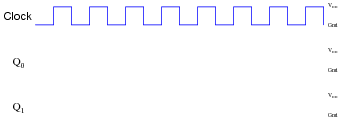
Reveal answerThis circuit counts down:

Notes:Discuss with your students how to relate timing diagrams to binary counts (as shown in the answer).
-
Question 8 of 34
Synchronous counter circuits tend to confuse students. The circuit shown here is the design that most students think ought to work, but actually doesn’t:

Shown here is an up/down synchronous counter design that does work:

Explain why this circuit is able to function properly (counting in either direction), while the first circuit is not able to count properly at all. What do those “extra” gates do to make the counter circuit function as it should. Hint: to more easily compare the up/down counter to the faulty up counter initially shown, connect the Up/[Down] control line high, and then disregard any lines and gates that become disabled as a result.
Reveal answerThe “extra” AND gates allow higher-level bits to toggle if and only if all preceding bits are high.
Notes:Although the up/down counter circuit may look overwhelmingly complex at first, it is actually quite simple once students recognize the intent of the AND and OR gates: to “select” either the Q or [Q] signal to control subsequent flip-flops.
-
Question 9 of 34
The following circuit is a two-bit synchronous binary up/down counter:

Explain what would happen if the upper AND gate’s output were to become “stuck” in the high state regardless of its input conditions. What effect would this kind of failure have on the counter’s operation?
Reveal answerThe counter would not be able to count in the üp” direction. When commanded to count that direction, the LSB would toggle between 0 and 1, but the MSB would not change state.
Notes:The purpose of this question is to get students to understand how a synchronous up/down counter works, in the context of analyzing the effects of a component failure.