Facebook
 Google
 GitHub
 Linkedin
Digital Circuits
Counters
34 questions By Tony R. Kuphaldt
-
Question 16 of 34
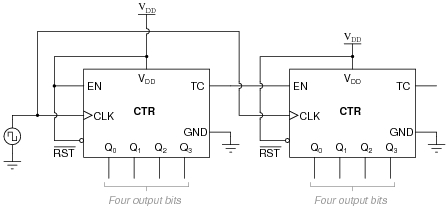
A student wishes to cascade multiple four-bit synchronous counters together. His first effort looks like this, and it works well as an eight-bit counter:
Encouraged by this success, the student decides to add another four-bit counter to the end to make a twelve-bit counter circuit:
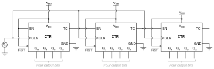
Unfortunately, this arrangement does not work so well. It seems to work good for the first 241 counts (from 000000000000 to 000011110000), but then the last four bits begin to cycle as quickly as the first four bits, while the middle four bits remain in the 1111 state for 15 additional clock pulses. Something is definitely very wrong here!
Determine what the problem is, and suggest a remedy for it. Hint: this situation is very similar to connecting more than two J-K flip-flops together to form a synchronous counter circuit.
Reveal answerThe “fix” for this problem is to enable the last (most significant) four-bit counter only when the terminal count (TC) outputs of both preceding counter circuits are active. I will let you figure out the details of this solution for yourself.
Notes:The “hint” in this question may give away too much, as the problem is precisely identical to the problem encountered with overly simplistic synchronous J-K flip-flop cascades. What new students tend to overlook is the necessity to enable successive stages only when all preceding stages are at their terminal counts. When you only have two stages (two J-K flip-flops or two IC counters) to deal with, there is only one TC output to be concerned with, and the problem never reveals itself.
Be sure to give your students time and opportunity to present their solutions to this dilemma. Ask them how they arrived at their solutions, whether by textbook, prior example (with J-K flip-flops), or perhaps sheer brain power.
-
Question 17 of 34
Some integrated circuit counters come equipped with multiple enable inputs. A good example of this is the 74HCT163:

In this case, as in others, the two enable inputs are not identical. Although both must be active for the counter to count, one of the enable inputs does something extra that the other one does not. This additional function is often referred to as a look-ahead carry, provided to simplify cascading of counters.
Explain what “look-ahead carry” means in the context of digital counter circuits, and why it is a useful feature.
Reveal answerThe “TE” input not only enables the count sequence, but it also enables the “terminal count” (TC) output which is used to cascade additional counter stages. This way, multiple synchronous counter stages may be connected together as simply as this:

Notes:The important lesson in this question is that synchronous counter circuits with more than two stages need to be configured in such a way that all higher-order stages are disabled with the terminal count of the lowest-order stage is inactive. This ensures a proper binary count sequence throughout the overall counter circuit’s range. Your students should have been introduced to this concept when studying synchronous counter circuits made of individual J-K flip-flops, and it is the same concept here.
Also important here is the realization that some IC counters come equipped with the “look-ahead” feature built in, and students need to know how and why to use this feature.
-
Question 18 of 34
Determine the modulus (MOD) of a four-bit binary counter. Determine the modulus of two four-bit binary counters cascaded to make an eight-bit binary counter.
Reveal answerFour bit counter modulus = 16.
Eight bit counter modulus = 256.
Follow-up question: is it possible for a four-bit counter to have a modulus equal to some value other than 16? Give an example!
Notes:The real purpose of this question is to get students to find out what term “modulus” means, and how it relates to counter bits.