Facebook
 Google
 GitHub
 Linkedin
Digital Circuits
Counters
34 questions By Tony R. Kuphaldt
-
Question 10 of 34
Supposed we used J-K flip-flops with asynchronous inputs (Preset and Clear) to build a counter:

With the asynchronous lines paralleled as such, what are we able to make the counter do now that we weren’t before we had asynchronous inputs available to us?
Reveal answerNow, we are able to force the counter to zero (0000) or full count (1111) at will.
Notes:Ask your students why this feature might be useful. Can they think of any applications involving a counter circuit where it would be practical to force its output to either zero or full count regardless of the clock’s action?
-
Question 11 of 34
The part number 74HCT163 integrated circuit is a high-speed CMOS, four-bit, synchronous binary counter. It is a pre-packaged unit, will all the necessary flip-flops and selection logic enclosed to make your design work easier than if you had to build a counter circuit from individual flip-flops. Its block diagram looks something like this (power supply terminals omitted, for simplicity):

Research the function of this integrated circuit, from manufacturers’ datasheets, and explain the function of each input and output terminal.
Reveal answer- P0, P1, P2, and P3 = parallel load data inputs
- Q0, Q1, Q2, and Q3 = count outputs
- CP = Clock pulse input
- [MR] = Master reset input
- [SPE] = Synchronous parallel enable input
- PE = Enable input
- TE = Enable input
- TC = Terminal count output (sometimes called ripple carry output, or RCO)
Follow-up question: both the reset ([MR]) and preset ([SPE]) inputs are synchronous for this particular counter circuit. Explain the significance of this fact in regard to how we use this IC.
Notes:Ultimately, your students will most likely be working with pre-packaged counters more often than counters made up of individual flip-flops. Thus, they need to understand the nomenclature of counters, their common pin functions, etc. If possible, allow for the group presentation of datasheets by having a computer projector available, so students may show the datasheets they’ve downloaded from the internet to the rest of the class.
Something your students may notice when researching datasheets is how different manufacturers give the same IC pins different names. This may make the interpretation of inputs and outputs on the given symbol more difficult, if the particular datasheet researched by the student does not use the same labels as I do! This is a great illustration of datasheet variability, covered in a way that students are not likely to forget.
-
Question 12 of 34
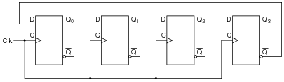
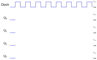
Determine the output pulses for this counter circuit, known as a Johnson counter, assuming that all Q outputs begin in the low state:
Reveal answer
Follow-up question: if used as a frequency divider, what is the input:output ratio of this circuit? How difficult would it be to design a Johnson counter with a different division ratio?
Notes:Discuss with your students how Johnson counters are quite different from binary-sequence counters, and how this uniqueness allows certain counting functions to be implemented much easier (using fewer gates) than other types of counter circuits.