Facebook
 Google
 GitHub
 Linkedin
AC Electric Circuits
Passive Filter Circuits
44 questions By Tony R. Kuphaldt
-
Question 28 of 44
Plot the typical frequency responses of four different filter circuits, showing signal output (amplitude) on the vertical axis and frequency on the horizontal axis:

Also, identify and label the bandwidth of the filter circuit on each plot.
Reveal answer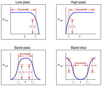
Notes:Although “bandwidth” is usually applied first to band-pass and band-stop filters, students need to realize that it applies to the other filter types as well. This question, in addition to reviewing the definition of bandwidth, also reviews the definition of cutoff frequency. Ask your students to explain where the 70.7% figure comes from. Hint: half-power point!
-
Question 29 of 44
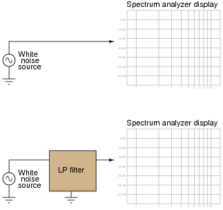
A white noise source is a special type of AC signal voltage source which outputs a broad band of frequencies (“noise”) with a constant amplitude across its rated range. Determine what the display of a spectrum analyzer would show if directly connected to a white noise source, and also if connected to a low-pass filter which is in turn connected to a white noise source:
Reveal answer
Notes:The purpose of this question, besides providing a convenient way to characterize a filter circuit, is to introduce students to the concept of a white noise source and also to strengthen their understanding of a spectrum analyzer’s function.
In case anyone happens to notice, be aware that the rolloff shown for this filter circuit is very steep! This sort of sharp response could never be realized with a simple one-resistor, one-capacitor (“first order”) filter. It would have to be a multi-stage analog filter circuit or some sort of active filter circuit.
-
Question 30 of 44
Predict how the operation of this second-order passive filter circuit will be affected as a result of the following faults. Consider each fault independently (i.e. one at a time, no multiple faults):

- Capacitor C1 fails open:
- Capacitor C2 fails shorted:
- Resistor R1 fails open:
- Resistor R2 fails open:
- Solder bridge (short) across resistor R2:
For each of these conditions, explain why the resulting effects will occur.
Reveal answer- Capacitor C1 fails open: No output signal at all.
- Capacitor C2 fails shorted: The circuit becomes a first-order filter with \(f_{cutoff}=\frac{R_1+R_2}{2 \pi R_1R_2C}\).
- Resistor R1 fails open: The circuit becomes a first-order filter with \(f_{cutoff}=\frac{C_1+C_2}{2 \pi R_2C_1C_2}\).
- Resistor R2 fails open: The circuit becomes a first-order filter with \(f_{cutoff}=\frac{1}{2 \pi R_1C_1}\) (assuming no load on the output).
- Solder bridge (short) across resistor R2: No output signal at all.
Notes:The purpose of this question is to approach the domain of circuit troubleshooting from a perspective of knowing what the fault is, rather than only knowing what the symptoms are. Although this is not necessarily a realistic perspective, it helps students build the foundational knowledge necessary to diagnose a faulted circuit from empirical data. Questions such as this should be followed (eventually) by other questions asking students to identify likely faults based on measurements.