Facebook
 Google
 GitHub
 Linkedin
AC Electric Circuits
Passive Filter Circuits
44 questions By Tony R. Kuphaldt
-
Question 34 of 44
An interesting technology dating back at least as far as the 1940’s, but which is still of interest today is power line carrier: the ability to communicate information as well as electrical power over power line conductors. Hard-wired electronic data communication consists of high-frequency, low voltage AC signals, while electrical power is low-frequency, high-voltage AC. For rather obvious reasons, it is important to be able to separate these two types of AC voltage quantities from entering the wrong equipment (especially the high-voltage AC power from reaching sensitive electronic communications circuitry).
Here is a simplified diagram of a power-line carrier system:
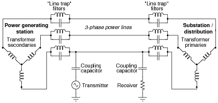
The communications transmitter is shown in simplified form as an AC voltage source, while the receiver is shown as a resistor. Though each of these components is much more complex than what is suggested by these symbols, the purpose here is to show the transmitter as a source of high-frequency AC, and the receiver as a load of high-frequency AC.
Trace the complete circuit for the high-frequency AC signal generated by the “Transmitter” in the diagram. How many power line conductors are being used in this communications circuit? Explain how the combination of “line trap” LC networks and “coupling” capacitors ensure the communications equipment never becomes exposed to high-voltage electrical power carried by the power lines, and visa-versa.
Reveal answer
Follow-up question #1: trace the path of line-frequency (50 Hz or 60 Hz) load current in this system, identifying which component of the line trap filters (L or C) is more important to the passage of power to the load. Remember that the line trap filters are tuned to resonate at the frequency of the communication signal (50-150 kHz is typical).
Follow-up question #2: coupling capacitor units used in power line carrier systems are special-purpose, high-voltage devices. One of the features of a standard coupling capacitor unit is a spark gap intended to “clamp” over voltages arising from lightning strikes and other transient events on the power line:

Explain how such a spark gap is supposed to work, and why it functions as an over-voltage protection device.
Notes:Although power line carrier technology is not used as much for communication in high-voltage distribution systems as it used to be - now that microwave, fiber optic, and satellite communications technology has superseded this older technique - it is still used in lower voltage power systems including residential (home) wiring. Ask your students if they have heard of any consumer technology capable of broadcasting any kind of data or information along receptacle wiring. “X10” is a mature technology for doing this, and at this time (2004) there are devices available on the market allowing one to plug telephones into power receptacles to link phones in different rooms together without having to add special telephone cabling.
Even if your students have not yet learned about three-phase power systems or transformers, they should still be able to discern the circuit path of the communications signal, based on what they know of capacitors and inductors, and how they respond to signals of arbitrarily high frequency.
Information on the coupling capacitor units was obtained from page 452 of the Industrial Electronics Reference Book, published by John Wiley & Sons in 1948 (fourth printing, June 1953). Although power line carrier technology is not as widely used now as it was back then, I believe it holds great educational value to students just learning about filter circuits and the idea of mixing signals of differing frequency in the same circuit.
-
Question 35 of 44
In this power-line carrier system, a pair of coupling capacitors connects a high-frequency “Transmitter” unit to two power line conductors, and a similar pair of coupling capacitors connects a “Receiver” unit to the same two conductors:
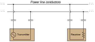
While coupling capacitors alone are adequate to perform the necessary filtering function needed by the communications equipment (to prevent damaged from the high-voltage electrical power also carried by the lines), that signal coupling may be made more efficient by the introduction of two line tuning units:
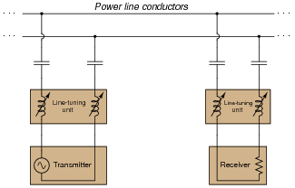
Explain why the addition of more components (in series, no less!) provides a better “connection” between the high-frequency Transmitter and Receiver units than coupling capacitors alone. Hint: the operating frequency of the communications equipment is fixed, or at least variable only over a narrow range.
Reveal answerThe introduction of the line-tuning units increases the efficiency of signal coupling by exploiting the principle of resonance between series-connected capacitors and inductors.
Challenge question: there are many applications in electronics where we couple high-frequency AC signals by means of capacitors alone. If capacitive reactance is any concern, we just use capacitors of large enough value that the reactance is minimal. Why would this not be a practical option in a power-line carrier system such as this? Why could we not (or why would we not) just choose coupling capacitors with very high capacitances, instead of adding extra components to the system?
Notes:Although power line carrier technology is not used as much for communication in high-voltage distribution systems as it used to be - now that microwave, fiber optic, and satellite communications technology has come of age - it is still used in lower voltage power systems including residential (home) wiring. Ask your students if they have heard of any consumer technology capable of broadcasting any kind of data or information along receptacle wiring. “X10” is a mature technology for doing this, and at this time (2004) there are devices available on the market allowing one to plug telephones into power receptacles to link phones in different rooms together without having to add special telephone cabling.
I think this is a really neat application of resonance: the complementary nature of inductors to capacitors works to overcome the less-than-ideal coupling provided by capacitors alone. Discuss the challenge question with your students, asking them to consider some of the practical limitations of capacitors, and how an inductor/capacitor resonant pair solves the line-coupling problem better than an oversized capacitor.
-
Question 36 of 44
The following circuit is called a twin-tee filter:

Research the equation predicting this circuit’s “notch” frequency, given the component value ratios shown.
fnotch = Reveal answerfnotch = 1 2 πR CNotes:Answering this question is simply a matter of research! There are many references a student could go to for information on twin-tee filters.