Facebook
 Google
 GitHub
 Linkedin
AC Electric Circuits
Passive Filter Circuits
44 questions By Tony R. Kuphaldt
-
Question 31 of 44
The Q factor of a series inductive circuit is given by the following equation:
Q = XL RseriesLikewise, we know that inductive reactance may be found by the following equation:
XL = 2 πf L We also know that the resonant frequency of a series LC circuit is given by this equation:
fr = 1 2 π √ LCThrough algebraic substitution, write an equation that gives the Q factor of a series resonant LC circuit exclusively in terms of L, C, and R, without reference to reactance (X) or frequency (f).
Reveal answer\(Q=\frac{1}{R}\sqrt\frac{L}{C}\)
Notes:This is merely an exercise in algebra. However, knowing how these three component values affects the Q factor of a resonant circuit is a valuable and practical insight!
-
Question 32 of 44
Calculate the resonant frequency, bandwidth, and half-power points of the following filter circuit:

Reveal answerfr = 6.79 kHz
Bandwidth = 289.4 Hz
f1 = 6.64 kHz
f2 = 6.93 kHz
Follow-up question: how would a decrease in the Q (“quality factor”) of the circuit affect the bandwidth, or would it at all?
Notes:The formulae required to calculate these parameters are easily obtained from any basic electronics text. No student should have trouble finding this information.
-
Question 33 of 44
Suppose a few turns of wire within the inductor in this filter circuit suddenly became short-circuited, so that the inductor effectively has fewer turns of wire than it did before:
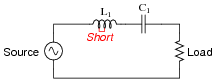
What sort of effect would this fault have on the filtering action of this circuit?
Reveal answerThe resonant frequency of the circuit would increase.
Challenge question: what would happen to the Q of this filter circuit as a result of the fault within the inductor?
Notes:Determining the effect on resonant frequency is a simple matter of qualitative analysis with the resonant frequency formula. The effect on Q (challenge question) may be answered just as easily if the students know the formula relating bandwidth to L, C, and R.