Facebook
 Google
 GitHub
 Linkedin
AC Electric Circuits
Passive Filter Circuits
44 questions By Tony R. Kuphaldt
-
Question 16 of 44
Calculate the power dissipated by this circuit’s load at two different source frequencies: 0 Hz (DC), and fcutoff.

What do these figures tell you about the nature of this filter circuit (whether it is a low-pass or a high-pass filter), and also about the definition of cutoff frequency (also referred to as f−3 dB)?
Reveal answerPload @ f = 0 Hz = 64 mW
Pload @ fcutoff = 32 mW
These load dissipation figures prove this circuit is a low-pass filter. They also demonstrate that the load dissipation at fcutoff is exactly half the amount of power the filter is capable of passing to the load under ideal (maximum) conditions.
Notes:If your students have never encountered decibel (dB) ratings before, you should explain to them that -3 dB is an expression meaning “one-half power,” and that this is why the cutoff frequency of a filter is often referred to as the half-power point.
The important lesson to be learned here about cutoff frequency is that its definition means something in terms of load power. It is not as though someone decided to arbitrarily define fcutoff as the point at which the load receives 70.7% of the source voltage!
-
Question 17 of 44
Filter circuits don’t just attenuate signals, they also shift the phase of signals. Calculate the amount of phase shift that these two filter circuits impart to their signals (from input to output) operating at the cutoff frequency:
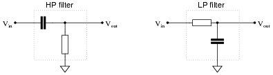
Reveal answerHP filter: Θ = +45o (Vout leads Vin)
LP filter: Θ = -45o (Vout lags Vin)
Notes:Note that no component values are given in this question, only the condition that both circuits are operating at the cutoff frequency. This may cause trouble for some students, because they are only comfortable with numerical calculations. The structure of this question forces students to think a bit differently than they might be accustomed to.
-
Question 18 of 44
Real filters never exhibit perfect “square-edge” Bode plot responses. A typical low-pass filter circuit, for example, might have a frequency response that looks like this:
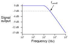
What does the term rolloff refer to, in the context of filter circuits and Bode plots? Why would this parameter be important to a technician or engineer?
Reveal answer“Rolloff” refers to the slope of the Bode plot in the attenuating range of the filter circuit, usually expressed in units of decibels per octave (dB/octave) or decibels per decade (dB/decade):
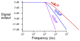
Notes:Point students’ attention to the scale used on this particular Bode plot. This is called a log-log scale, where neither vertical nor horizontal axis is linearly marked. This scaling allows a very wide range of conditions to be shown on a relatively small plot, and is very common in filter circuit analysis.