Facebook
 Google
 GitHub
 Linkedin
AC Electric Circuits
Passive Filter Circuits
44 questions By Tony R. Kuphaldt
-
Question 7 of 44
The following schematic shows the workings of a simple AM radio receiver, with transistor amplifier:

The “tank circuit” formed of a parallel-connected inductor and capacitor network performs a very important filtering function in this circuit. Describe what this filtering function is.
Reveal answerThe “tank circuit” filters out all the unwanted radio frequencies, so that the listener hears only one radio station broadcast at a time.
Follow-up question: how might a variable capacitor be constructed, to suit the needs of a circuit such as this? Note that the capacitance range for a tuning capacitor such as this is typically in the pico-Farad range.
Notes:Challenge your students to describe how to change stations on this radio receiver. For example, if we are listening to a station broadcasting at 1000 kHz and we want to change to a station broadcasting at 1150 kHz, what do we have to do to the circuit?
Be sure to discuss with them the construction of an adjustable capacitor (air dielectric).
-
Question 8 of 44
Draw the Bode plot for an ideal high-pass filter circuit:

Be sure to note the “cutoff frequency” on your plot.
Reveal answer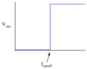
Follow-up question: a theoretical filter with this kind of idealized response is sometimes referred to as a “brick wall” filter. Explain why this name is appropriate.
Notes:The plot given in the answer, of course, is for an ideal high-pass filter, where all frequencies below fcutoff are blocked and all frequencies above fcutoff are passed. In reality, filter circuits never attain this ideal “square-edge” response. Discuss possible applications of such a filter with your students.
Challenge them to draw the Bode plots for ideal band-pass and band-stop filters as well. Exercises such as this really help to clarify the purpose of filter circuits. Otherwise, there is a tendency to lose perspective of what real filter circuits, with their correspondingly complex Bode plots and mathematical analyses, are supposed to do.
-
Question 9 of 44
Draw the Bode plot for an ideal low-pass filter circuit:

Be sure to note the “cutoff frequency” on your plot.
Reveal answer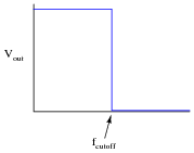
Follow-up question: a theoretical filter with this kind of idealized response is sometimes referred to as a “brick wall” filter. Explain why this name is appropriate.
Notes:The plot given in the answer, of course, is for an ideal low-pass filter, where all frequencies below fcutoff are passed and all frequencies above fcutoff are blocked. In reality, filter circuits never attain this ideal “square-edge” response. Discuss possible applications of such a filter with your students.
Challenge them to draw the Bode plots for ideal band-pass and band-stop filters as well. Exercises such as this really help to clarify the purpose of filter circuits. Otherwise, there is a tendency to lose perspective of what real filter circuits, with their correspondingly complex Bode plots and mathematical analyses, are supposed to do.