Facebook
 Google
 GitHub
 Linkedin
AC Electric Circuits
Passive Filter Circuits
44 questions By Tony R. Kuphaldt
-
Question 37 of 44
Suppose this band-stop filter were to suddenly start acting as a high-pass filter. Identify a single component failure that could cause this problem to occur:
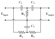
Reveal answerIf resistor R3 failed open, it would cause this problem. However, this is not the only failure that could cause the same type of problem!
Notes:Ask your students to explain why an open R2 would cause this filter to act as a high-pass instead of a band-stop. Then, ask them to identify other possible component failures that could cause a similar effect.
By the way, this filter circuit illustrates the popular twin-tee filter topology.
-
Question 38 of 44
Examine the following schematic diagram for an audio tone control circuit:

Determine which potentiometer controls the bass (low frequency) tones and which controls the treble (high frequency) tones, and explain how you made those determinations.
Reveal answer
Notes:The most important answer to this question is how your students arrived at the correct potentiometer identifications. If none of your students were able to figure out how to identify the potentiometers, give them this tip: use the superposition theorem to analyze the response of this circuit to both low-frequency signals and high-frequency signals. Assume that for bass tones the capacitors are opaque (Z = ∞) and that for treble tones they are transparent (Z = 0). The answers should be clear if they follow this technique.
This general problem-solving technique - analyzing two or more “extreme” scenarios to compare the results - is an important one for your students to become familiar with. It is extremely helpful in the analysis of filter circuits!
-
Question 39 of 44
Examine the following audio tone control circuit, used to control the balance of bass and treble heard at the headphones from an audio source such as a radio or CD player:
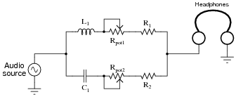
Suppose that after working just fine for quite a long while, suddenly no more bass tones were heard through the headphones. Identify at least two component or wiring faults that could cause this to happen.
Reveal answerHere are some possibilities:
- R1 failed open
- Rpot1 failed open
- L1 failed open
- Open wire connections between any of the above listed components
Notes:The circuit shown in the question is not very practical for direct headphone use, unless low-value resistors are used. Otherwise, the losses are too great and maximum volume suffers. An improvement over the original circuit is one where a matching transformer is used to effectively increase the impedance of the headphones: