Facebook
 Google
 GitHub
 Linkedin
Digital Circuits
Performance-Based Assessments for Digital Circuit Competencies
43 questions By Tony R. Kuphaldt
-
Question 22 of 43

Reveal answerUse circuit simulation software to verify your predicted and actual truth tables.
Notes:It should be noted that the input states in this circuit are defined by the voltage levels, not by the contact status. In other words, a closed contact equals a “low” (0) logic state.
Suggested truth tables include the following (encoded as Boolean SOP statements):
- \({AB}\bar{C} + {ABC}\)
- \(\bar{A}{B}\bar{C} + \bar{A}{BC}\)
- \(\bar{A}{B}\bar{C} + \bar{A}{BC} + \bar{A}\bar{B}\bar{C}\)
- \({A}\bar{B}\bar{C} + {A}\bar{B}{C}\)
- \({A}{B}\bar{C} + {A}\bar{B}\bar{C} + \bar{A}\bar{B}\bar{C}\)
- \(\bar{A}{B}{C} + \bar{A}\bar{B}{C} + \bar{A}\bar{B}\bar{C}\)
- \({A}{B}{C} + \bar{A}{B}{C} + {A}{B}\bar{C}\)
- \({A}\bar{B}{C} + \bar{A}\bar{B}{C} + \bar{A}\bar{B}\bar{C}\)
- \({A}{B}{C} + {A}\bar{B}{C} + \bar{A}\bar{B}{C}\)
I strongly recommend having students build their logic circuits with CMOS chips rather than TTL, because of the less stringent power supply requirements of CMOS. I also recommend drawing a combinational circuit using four gates, because this is the common number of two-input gates found on 14-pin DIP logic chips.
-
Question 23 of 43

Reveal answerUse circuit simulation software to verify your predicted and actual truth tables.
Notes:It should be noted that the input states in this circuit are defined by the voltage levels, not by the contact status. In other words, a closed contact equals a “low” (0) logic state.
Here, the arrangement of the input letters D, C, B, and A is purposeful: D represents the most significant bit, while A represents the least significant bit, just like the IC datasheets typically order the input lines.
Normally, I draw LEDs in the schematic to give visual indication of output states. Here, due to the sheer number of required LEDs (16), I decided not to. However, students with access to lots of LEDs may choose to add them to their circuits, because visual indicators do make the circuit’s function easier to understand.
If the decoder IC has enable inputs, the students must figure out what to do with them to make the circuit function!
-
Question 24 of 43
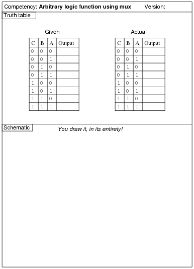
Reveal answerUse circuit simulation software to verify your predicted and actual truth tables.
Notes:The purpose of this exercise is for students to connect a multiplexer to fulfill an arbitrary logic function specified by the instructor, thus showing the flexibility of the technique.
Here, the arrangement of the input letters C, B, and A is purposeful: C represents the most significant bit, while A represents the least significant bit, just like the IC datasheets typically order the input lines.