
 Facebook
 Google
 GitHub
 Linkedin
Discrete Semiconductor Devices and Circuits
Oscillator Circuits
49 questions By Tony R. Kuphaldt
-
Question 28 of 49
Identify some realistic component failures that would definitely prevent this oscillator circuit from oscillating:

For each of the faults you propose, explain why the oscillations will cease.
Reveal answerNote: The fault list shown here is not comprehensive.
- Solder bridge shorting across any of the phase-shift resistors (R1 through R3).
- Resistor R4 failing open.
- Transistor Q1 failing in any mode.
Follow-up question: how would you rank the listed faults in order of probability? In other words, which of these faults do you suppose would be more likely than the others, least likely than the others, etc.?
Notes:The purpose of this question is to approach the domain of circuit troubleshooting from a perspective of assessing probable faults given very limited information about the circuit’s behavior. An important part of troubleshooting is being able to decide what faults are more likely than others, and questions such as this help develop that skill.
-
Question 29 of 49
Suppose some of the turns of wire (but not all) in the primary winding of the transformer were to fail shorted in this Armstrong oscillator circuit:
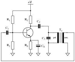
How would this effective decreasing of the primary winding turns affect the operation of this circuit? What if it were the secondary winding of the transformer to suffer this fault instead of the primary?
Reveal answerA partially shorted primary winding will result in increased frequency and (possibly) increased distortion in the output signal. A partially shorted secondary winding may result in oscillations ceasing altogether!
Notes:The purpose of this question is to approach the domain of circuit troubleshooting from a perspective of knowing what the fault is, rather than only knowing what the symptoms are. Although this is not necessarily a realistic perspective, it helps students build the foundational knowledge necessary to diagnose a faulted circuit from empirical data. Questions such as this should be followed (eventually) by other questions asking students to identify likely faults based on measurements.
-
Question 30 of 49
A technician is given a transistor testing circuit to repair. This simple circuit is an audio-frequency oscillator, and has the following schematic diagram:
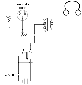
After repairing a broken solder joint, the technician notices that the DPDT switch has lost its label. The purpose of this switch is to allow polarity to be reversed so as to test both PNP and NPN transistor types. However, the label showing which direction is for NPN and which direction is for PNP has fallen off. And, to make matters worse, the schematic diagram does not indicate which position is which.
Determine what the proper DPDT switch label should be for this transistor tester, and explain how you know it is correct. Note: you do not even have to understand how the oscillator circuit works to be able to determine the proper switch label. All you need to know is the proper voltage polarities for NPN and PNP transistor types.
Reveal answerLeft is NPN, and right is PNP.
Notes:This is a very realistic problem for a technician to solve. Of course, one could determine the proper switch labeling experimentally (by trying a known NPN or PNP transistor and seeing which position makes the oscillator work), but students need to figure this problem out without resorting to trial and error. It is very important that they learn how to properly bias transistors!
Be sure to ask your students to explain how they arrived at their conclusion. It is not good enough for them to simply repeat the given answer!


