Facebook
 Google
 GitHub
 Linkedin
Discrete Semiconductor Devices and Circuits
Oscillator Circuits
49 questions By Tony R. Kuphaldt
-
Question 25 of 49
Predict how the operation of this sawtooth-wave oscillator circuit will be affected as a result of the following faults. Consider each fault independently (i.e. one at a time, no multiple faults):

- Capacitor C1 fails shorted:
- Resistor R1 fails open:
- JFET fails shorted (drain-to-source):
- Resistor R3 fails open:
For each of these conditions, explain why the resulting effects will occur.
Reveal answer- Capacitor C1 fails shorted: No oscillation, low DC voltage output.
- Resistor R1 fails open: No oscillation, low DC voltage output.
- JFET fails shorted (drain-to-source): Oscillation waveform looks “rounded” instead of having a straight leading edge, frequency is higher than normal.
- Resistor R3 fails open: No oscillation, high DC voltage output.
Notes:The purpose of this question is to approach the domain of circuit troubleshooting from a perspective of knowing what the fault is, rather than only knowing what the symptoms are. Although this is not necessarily a realistic perspective, it helps students build the foundational knowledge necessary to diagnose a faulted circuit from empirical data. Questions such as this should be followed (eventually) by other questions asking students to identify likely faults based on measurements.
-
Question 26 of 49
Predict how the operation of this astable multivibrator circuit will be affected as a result of the following faults. Specifically, identify the final states of the transistors (on or off) resulting from each fault. Consider each fault independently (i.e. one at a time, no multiple faults):

- Capacitor C1 fails open:
- Capacitor C2 fails open:
- Resistor R1 fails open:
- Resistor R2 fails open:
- Resistor R3 fails open:
- Resistor R4 fails open:
For each of these conditions, explain why the resulting effects will occur.
Reveal answer- Capacitor C1 fails open: Q2 immediately on, Q1 on after short time delay.
- Capacitor C2 fails open: Q1 immediately on, Q2 on after short time delay.
- Resistor R1 fails open: Q2 on, Q1 will have base current but no collector current.
- Resistor R2 fails open: Q1 on, Q2 off.
- Resistor R3 fails open: Q2 on, Q1 off.
- Resistor R4 fails open: Q1 on, Q2 will have base current but no collector current.
Notes:The purpose of this question is to approach the domain of circuit troubleshooting from a perspective of knowing what the fault is, rather than only knowing what the symptoms are. Although this is not necessarily a realistic perspective, it helps students build the foundational knowledge necessary to diagnose a faulted circuit from empirical data. Questions such as this should be followed (eventually) by other questions asking students to identify likely faults based on measurements.
-
Question 27 of 49
Predict how the operation of this astable multivibrator circuit will be affected as a result of the following faults. Specifically, identify the signals found at test points TP1, TP2, TP3, and Vout resulting from each fault. Consider each fault independently (i.e. one at a time, no multiple faults):
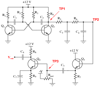
- Resistor R4 fails open:
- Resistor R5 fails open:
- Resistor R7 fails open:
- Resistor R9 fails open:
- Capacitor C7 fails shorted:
- Capacitor C4 fails shorted:
- Capacitor C5 fails open:
- Transistor Q3 fails open (collector-to-emitter):
For each of these conditions, explain why the resulting effects will occur.
Reveal answer- Resistor R4 fails open: Zero volts DC and AC at all four test points except for TP3 where there will be normal DC bias voltage.
- Resistor R5 fails open: Normal signal at TP1, zero volts AC and DC at all other test points except for TP3 where there will be normal DC bias voltage.
- Resistor R7 fails open: Normal signals at TP1 and at TP2, zero volts AC and DC at all other test points except for TP3 where there will be normal DC bias voltage.
- Resistor R9 fails open: Normal signals at TP1, at TP2, and at TP3, but zero volts AC and DC at Vout.
- Capacitor C7 fails shorted: Normal AC signals at TP1, at TP2, and at TP3, badly distorted waveform at Vout, only about 0.7 volts DC bias at TP3.
- Capacitor C4 fails shorted: Normal signal at TP1, zero volts AC and DC at all other test points except for TP3 where there will be normal DC bias voltage.
- Capacitor C5 fails open: Normal signals at TP1 and at TP2, zero volts AC and DC at all other test points except for TP3 where there will be normal DC bias voltage.
- Transistor Q3 fails open (collector-to-emitter): Normal signals at TP1 and at TP2, zero volts AC and DC at all other test points except for TP3 where there will be normal DC bias voltage.
Notes:The purpose of this question is to approach the domain of circuit troubleshooting from a perspective of knowing what the fault is, rather than only knowing what the symptoms are. Although this is not necessarily a realistic perspective, it helps students build the foundational knowledge necessary to diagnose a faulted circuit from empirical data. Questions such as this should be followed (eventually) by other questions asking students to identify likely faults based on measurements.