Facebook
 Google
 GitHub
 Linkedin
AC Electric Circuits
Passive Integrator and Differentiator Circuits
25 questions By Tony R. Kuphaldt
-
Question 13 of 25
Design a passive integrator circuit using a resistor and inductor rather than a resistor and capacitor:
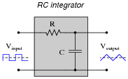
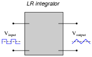
In addition to completing the inductor circuit schematic, qualitatively state the preferred values of L and R to achieve an output waveform most resembling a true triangle wave. In other words, are we looking for a large or small inductor; a large or small resistor?
Reveal answer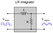
For maximum “triangle-like” waveshape, choose a large value for L and a small value for R.
Follow-up question: explain how the choices of values for L and R follow the same reasoning as the choices for R and C in an RC passive integrator circuit.
Notes:Explain to your students that although LR integrator circuits are possible, they are almost never used. RC circuits are much more practical. Ask them to determine why this is!
-
Question 14 of 25
When you look at the schematic diagram for a passive integrator circuit, it ought to remind you of another type of circuit you’ve seen before: a passive filter circuit:
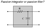
What specific type of passive filter does a passive integrator circuit resemble? Is the resemblance the same for LR integrators as well, or just RC integrators? What does this resemblance tell you about the frequency response of a passive integrator circuit?
Reveal answerThe answer to this question is so easy for you to research, it would be an insult to print it here!
Notes:This question is fairly easy, and provides a logical step to prepare students for frequency-domain analysis of passive integrator circuits.
-
Question 15 of 25
A “cheap” way to electronically produce waveforms resembling sine waves is to use a pair of passive integrator circuits, one to convert square waves into pseudo-triangle waves, and the next to convert pseudo-triangle waves into pseudo-sine waves:
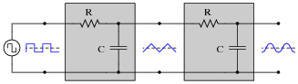
From Fourier’s theory, we know that a square wave is nothing more than a series of sinusoidal waveforms: the fundamental frequency plus all odd harmonics at diminishing amplitudes. Looking at the two integrators as passive filter circuits, explain how it is possible to get a pseudo-sine wave from a square wave input as shown in the above diagram. Also, explain why the final output is not a true sine wave, but only resembles a sine wave.
Reveal answerThese two integrators act as a second-order lowpass filter, attenuating the harmonics in the square wave far more than the fundamental.
Challenge question: does the output waveshape more closely resemble a sine wave when the source frequency is increased or decreased?
Notes:Once students have a conceptual grasp on Fourier theory (that non-sinusoidal waveshapes are nothing more than series of superimposed sinusoids, all harmonically related), they possess a powerful tool for understanding new circuits such as this. Of course, it is possible to understand a circuit such as this from the perspective of the time domain, but being able to look at it from the perspective of the frequency domain provides one more layer of insight.
Incidentally, one may experiment with such a circuit using 0.47 μF capacitors, 1 kΩ resistors, and a fundamental frequency of about 3 kHz. Viewing the output waveform amplitudes with an oscilloscope is insightful, especially with regard to signal amplitude!