
 Facebook
 Google
 GitHub
 Linkedin
DC Electric Circuits
Kirchhoff’s Laws
48 questions By Tony R. Kuphaldt
-
Question 43 of 48
Calculate and label the currents at each node (junction point) in this circuit:

Reveal answer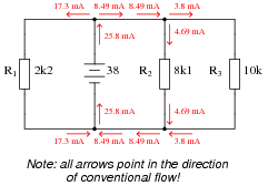
Notes:Discuss with your students techniques for calculating the node currents. What Laws did your students apply, and more importantly, in what order did they apply them?
-
Question 44 of 48
Determine the current through battery #2 in this power system, if the generator is outputting 50 amps, battery #1 is charging at a rate of 22 amps, and the light bulbs draw 5 amps of current each. Be sure to indicate whether battery #2 is charging or discharging:
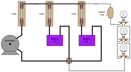
Reveal answerBattery #2 is charging at a rate of 13 amps.
Notes:Perhaps the most difficult portion of this question for students to figure out is which way current goes when a battery is charging, versus when it is discharging. Thus, it is a good review for students on secondary battery theory!
Another challenge for students might be where to label a “node” for the algebraic summation of currents. Do not simply tell them, but rather let them choose the node.
-
Question 45 of 48
Explain how an analog ammeter could be used to measure the current output of the generator in this circuit, as it charges the two batteries and energizes the three light bulbs. Be sure to connect the ammeter in the circuit in such a way that the meter needle does not drive “downscale”!
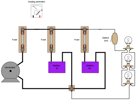
Reveal answerTo measure generator output current, remove the fuse and connect the ammeter test leads to the two “clips” of the empty fuse holder, the red lead on the clip connecting to the generator, and the black lead on the clip connecting to the battery.
Follow-up question: describe any relevant safety procedures and considerations necessary prior to performing this task.
Notes:Be sure to reinforce the safety aspects of this task. Although the primary focus of this question is most definitely Kirchhoff’s Current Law, that is no excuse to avoid discussing electrical safety!



I think there is a mistake in question 28 more specifically step 3 and 4. I think their answers are switched. Step 3 should be 12 and Step 4 should be -24
In the notes for question 4, the diagram should have a 47k resistor, not 4.7k.