
 Facebook
 Google
 GitHub
 Linkedin
DC Electric Circuits
Kirchhoff’s Laws
48 questions By Tony R. Kuphaldt
-
Question 19 of 48
Determine the voltages registered by a voltmeter between the following points in this circuit:

VA = (red lead on A, black lead on ground)
VB = (red lead on B, black lead on ground)
VC = (red lead on C, black lead on ground)
VD = (red lead on D, black lead on ground)
VAC = (red lead on A, black lead on C)
VDB = (red lead on D, black lead on B)
VBA = (red lead on B, black lead on A)
VBC = (red lead on B, black lead on C)
VCD = (red lead on C, black lead on D)
Reveal answerVA = 13 volts (red lead on A, black lead on ground)
VB = 4 volts (red lead on B, black lead on ground)
VC = 7 volts (red lead on C, black lead on ground)
VD = -6 volts (red lead on D, black lead on ground)
VAC = 6 volts (red lead on A, black lead on C)
VDB = -10 volts (red lead on D, black lead on B)
VBA = -9 volts (red lead on B, black lead on A)
VBC = -3 volts (red lead on B, black lead on C)
VCD = 13 volt (red lead on C, black lead on D)
Notes:Discuss with your students multiple techniques of solving for these voltages, asking them first for their solution strategies.
-
Question 20 of 48
Suppose you wanted to measure the amount of current going through resistor R2 on this printed circuit board, but did not have the luxury of breaking the circuit to do so (unsoldering one end of the resistor, detaching it from the PCB, and connecting an ammeter in series). All you can do while the circuit is powered is measure voltage with a voltmeter:
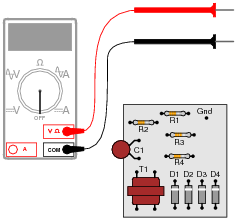
So, you decide to touch the black probe of the voltmeter to the circuit’s “Gnd” (ground) test point, and measure the voltage with reference to ground on both sides of R2. The results are shown here:
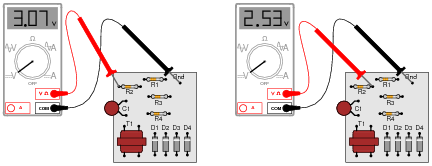
R2’s color code is Orange, Orange, Red, Gold. Based on this information, determine both the direction and the magnitude of DC current through resistor R2, and explain how you did so.
Reveal answerIR2 ≈ 160 μA, conventional flow from left to right (electron flow from right to left).
Follow-up question: this technique for estimating resistor current depends on one important assumption. Describe what this assumption is, and how the accuracy of your current calculation may be affected if the assumption is invalid.
Notes:This is a good example of how Kirchhoff’s Voltage Law is more than just an abstract tool for mathematical analysis - it is also a powerful technique for practical circuit diagnosis. Students must apply KVL to determine the voltage drop across R2, and then use Ohm’s Law to calculate its current.
If students experience difficulty visualizing how KVL plays a part in the solution of this problem, show them this illustration:

-
Question 21 of 48
Shown here is a simple telegraph circuit:

Explain why the lamps energize when either pushbutton is actuated, and why they de-energize when both pushbuttons are open (despite there being an unbroken circuit connecting both lamps and both batteries).
Reveal answerThe key to understanding this circuit is that both batteries are equal in voltage and opposed in polarity to one another.
Notes:This is a simple circuit, yet practical in its function as a telegraph and as an example of KVL in action.




I think there is a mistake in question 28 more specifically step 3 and 4. I think their answers are switched. Step 3 should be 12 and Step 4 should be -24
In the notes for question 4, the diagram should have a 47k resistor, not 4.7k.