
 Facebook
 Google
 GitHub
 Linkedin
DC Electric Circuits
Kirchhoff’s Laws
48 questions By Tony R. Kuphaldt
-
Question 28 of 48
Imagine you are using a digital voltmeter to measure voltages between pairs of points in a circuit, following the sequence of steps shown in the following diagrams:
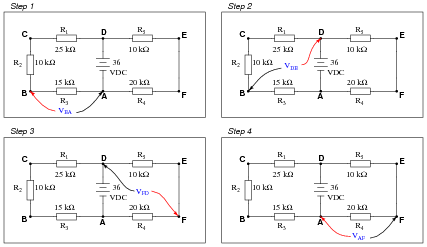
How much voltage would be registered by the voltmeter in each of the steps? Be sure to include the sign of the DC voltage measured (note the coloring of the voltmeter leads, with the red lead always on the first point denoted in the subscript: VBA = red lead on “B” and black lead on “A”):
- VBA =
- VDB =
- VFD =
- VAF =
What is the algebraic sum of these voltages?
Reveal answer- VBA = 10.8 volts
- VDB = 25.2 volts
- VFD = −12.0 volts
- VAF = −24.0 volts
Notes:Ask your students this question: “Will the algebraic sum of voltage measurements ever be other than zero in a loop?” Ask them to explain why this is, as best they can.
-
Question 29 of 48
Suppose you were measuring the voltage between “test points” TP1 and TP2 on this printed circuit board, where the circuit receives DC power from a voltage source. Suddenly, this voltage decreases. Wondering if perhaps the power supply voltage itself decreased, you go back to measure its output voltage and find that it is unchanged from before:
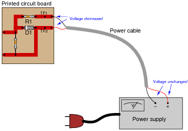
Based on your knowledge of Kirchhoff’s Voltage Law, what must have happened to cause the voltage between TP1 and TP2 on the circuit board to suddenly decrease, given the power supply’s stable voltage output? Hint: the components on the circuit board are irrelevant to the answer!
Reveal answerThere must be a voltage drop(s) somewhere in the power cable between test points TP1/TP2 and the power supply. For example, an increased resistance due to fraying wires would cause a voltage drop at VTP1−TP2 with a constant supply voltage.
Notes:Ask your students where the increased voltage drop(s) might be located in this circuit. It might be helpful to draw the test points, power cable, and power supply as a circuit, using standard schematic symbols. Ask your students, “What type of fault might cause such voltage drop increases in this loop?”
-
Question 30 of 48
When electricity and electronics students begin learning about series circuits and Kirchhoff’s Voltage Law, they are often mercilessly subjected to circuits such as this:

A common (and legitimate!) question asked by students is, “Where would we ever encounter a circuit such as this, with batteries opposing each other?” In practice, it is rare to find electrochemical batteries intentionally connected in such a manner, with some aiding and some opposing. However, there are many practical applications where the voltages involved are not intentional, but rather are unavoidable potentials created by junctions of dissimilar materials. Take for instance the application of EKG (electrocardiogram) measurements, where metal electrodes must be placed in contact with a human body to intercept tiny voltage signals from the contracting heart muscles:

A junction of metal wire to human skin is surprisingly complex from an electrical perspective, and may be approximately modeled by the following collection of idealized components:
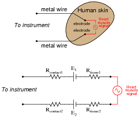
Resistors Rcontact1 and Rcontact2 represent electrical resistance between the metal electrodes and skin at the point of contact. Resistors Rtissue1 and Rtissue2 represent electrical resistance of human tissue between the points of electrode contact and the actual heart muscle. The two series-opposing potentials (E1 and E2) are not intentional, but rather the result of electrochemical action between the metal electrode surfaces and human skin. They cannot be eliminated, but their combined effect is minimal because they are approximately equal in magnitude. Explain how Kirchhoff’s Voltage Law applies to this equivalent circuit, especially how the biomedical instrument “sees” only the heart muscle voltage signal and neither of the skin-contact potentials.
Reveal answerApplying KVL to the circuit loop, we find that equal contact potentials E1 and E2 cancel each other out, leaving only the heart muscle voltage to be present at the instrument terminals.
Follow-up question: why is the heart muscle represented in the equivalent circuit by an AC voltage source symbol rather than by a DC voltage source symbol (battery)? Does this matter when we apply KVL to the loop? Why or why not?
Notes:The question of “where will we ever see this?” is too often ignored by teachers, who forget the lack of context present in their new students’ understanding. Remember that this is all new to most of your students, so they lack the years of experience you have working with circuits in practical scenarios. A question like this deserves to be answered, and answered well.
Truth be known, the equivalent circuit for electrode-to-skin contact is far more complex than what is shown here (impedances everywhere!), but the point here is to simplify it enough so that students studying DC circuits and KVL would be able to grasp it.
Electrode half-cell potentials (E1 and E2 in the equivalent schematic diagram) caused by electrochemical action are not the only source of stray potentials in measurement circuits by any means! Noise voltage is a consideration in many circumstances (whether induced by outside sources or generated by physical action such as Johnson noise), thermal voltages caused by junctions of dissimilar metals, and others. If all we are doing is making crude measurements, these stray voltages will be of little concern. If precision is necessary, which is often the case in medical and scientific measurements, these spurious voltages can be devastating.



I think there is a mistake in question 28 more specifically step 3 and 4. I think their answers are switched. Step 3 should be 12 and Step 4 should be -24
In the notes for question 4, the diagram should have a 47k resistor, not 4.7k.