
 Facebook
 Google
 GitHub
 Linkedin
DC Electric Circuits
Kirchhoff’s Laws
48 questions By Tony R. Kuphaldt
-
Question 46 of 48
Suppose you are asked to determine whether or not each battery in this circuit is charging or discharging:
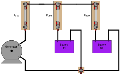
To do so, of course, you need to determine the direction of current through each battery. Unfortunately, your multimeter does not have the current rating necessary to directly measure such large currents, and you do not have access to a clamp-on (magnetic) ammeter capable of measuring DC current.
You are about to give up when a master technician comes along and uses her multimeter (set to measure millivolts) to take these three voltage measurements:
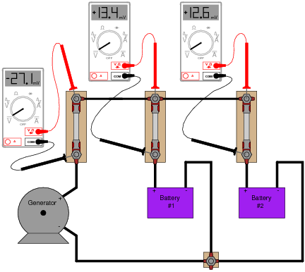
“There,” she says, ït’s easy!” With that, she walks away, leaving you to figure out what those measurements mean. Determine the following:
- •
- How these DC millivoltage measurements indicate direction of current.
- •
- Whether or not each battery is charging or discharging.
- •
- Whether or not these millivoltage measurements can tell you how much current is going through each battery.
- •
- How this general principle of measurement may be extended to other practical applications.
Reveal answerThe master technician exploited the inherent resistance of each fuse as a current-indicating shunt resistor. The measurements indicate both batteries are charging.
Notes:This is a very practical (and handy!) method of qualitative current measurement I’ve used many times on the job. Fuses, as well as other current-handling components, always have some non-zero amount of electrical resistance between their terminals, which means they are usable as crude shunt resistors. Their actual resistance will most likely be unknown to you, which is why they are useful in this capacity as qualitative measurement devices only, not quantitative.
Some students may point out that the measurement taken across the generator’s fuse is not necessary to determine battery charging status. Technically, this is true, but doing so helps to confirm the validity of this technique. The polarity of that measurement does indeed show (conventional flow) current to be going upward through the generator fuse, versus downward through the battery fuses.
Students may also point out that the battery fuse millivoltage measurements do not add up to equal the generator fuse millivoltage measurement, as Kirchhoff’s Current Law (KCL) would suggest. This is one example showing how the technique is strictly qualitative, not quantitative. We have no idea how much resistance lies within each fuse, and so we cannot rely on the millivoltage measurements as being proportional to current. This is especially true if the fuses are not identical!
Other circuit elements lending themselves to this same sort of application include overload “heater” elements for motor control circuits, long lengths of wire (provided you can stretch your millivolt-meter leads to reach both ends), circuit breakers, (closed) switches, and wire connections (particularly if the connection is old and possibly corroded).
-
Question 47 of 48
The generator in this power system is disconnected for routine servicing by removing its fuse, leaving the two batteries to supply all power to the bank of light bulbs:
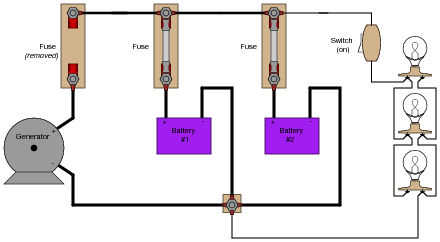
The two batteries are rated such that they are supposed to provide at least 10 hours of back-up power in the event of a generator “outage” such as this. Unfortunately, the light bulbs begin to dim much sooner than expected. Something is wrong in the system, and you are asked to figure out what.
Explain what steps you would take to diagnose the problem in this circuit, commenting on any relevant safety measures taken along the way.
Reveal answerOne simple procedure would be to connect a voltmeter in parallel with the light bulb bank, then remove the fuse for battery #1 and note the decrease in bus voltage. After that, replace the fuse for battery #1 and then remove the fuse for battery #2, again noting the decrease in bus voltage. If there is a problem with one of the batteries, it will be evident in this test. If both batteries are in good condition, but simply low on charge, that will also be evident in this test.
Notes:I purposely avoided giving away explicit answers in the Answer section of this question, electing instead to simply provide a sound procedure. The point here is for students to figure out on their own what the voltmeter indications would mean with regard to battery condition.
-
Question 48 of 48
Although the voltage divider and current divider equations are very useful in circuit analysis, they are easily confused for one another because they look so similar:
VR = Vtotal ( R Rtotal) Vs. IR = Itotal ( Rtotal R) Specifically, it is easy to forget which way the resistance fraction goes for each one. Is it [R/(Rtotal)] or is it [(Rtotal)/R] ? Simply trying to memorize which fraction form goes with which equation is a bad policy, since memorization of arbitrary forms tends to be unreliable. What is needed is recognition of some sort of principle that makes the form of each equation sensible. In other words, each equation needs to make sense why it is the way it is.
Explain how one would be able to tell that the following equations are wrong, without referring to a book:
VR = Vtotal ( Rtotal R) Wrong equations! IR = Itotal ( R Rtotal) Reveal answerThe resistance fraction must always be less than 1.



I think there is a mistake in question 28 more specifically step 3 and 4. I think their answers are switched. Step 3 should be 12 and Step 4 should be -24
In the notes for question 4, the diagram should have a 47k resistor, not 4.7k.