Facebook
 Google
 GitHub
 Linkedin
Discrete Semiconductor Devices and Circuits
Performance-Based Assessments for Semiconductor Circuit Competencies
62 questions By Tony R. Kuphaldt
-
Question 31 of 62
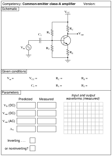
Reveal answerUse circuit simulation software to verify your predicted and measured parameter values.
Notes:Use a variable-voltage, regulated power supply to supply any amount of DC voltage below 30 volts. Specify standard resistor values, all between 1 kΩ and 100 kΩ (1k5, 2k2, 2k7, 3k3, 4k7, 5k1, 6k8, 10k, 22k, 33k, 39k 47k, 68k, etc.). Use a sine-wave function generator to supply an audio-frequency input signal, and make sure its amplitude isn’t set so high that the amplifier clips.
I have had good success using the following values:
- VCC = 9 volts
- Vin = audio-frequency signal, 0.5 volt peak-to-peak
- R1 = 220 kΩ
- R2 = 27 kΩ
- RC = 10 kΩ
- RE = 1.5 kΩ
- C1 = 10 μF
An extension of this exercise is to incorporate troubleshooting questions. Whether using this exercise as a performance assessment or simply as a concept-building lab, you might want to follow up your students’ results by asking them to predict the consequences of certain circuit faults.
-
Question 32 of 62

Reveal answerUse circuit simulation software to verify your predicted and measured parameter values.
Notes:Use a variable-voltage, regulated power supply to supply any amount of DC voltage below 30 volts. Specify standard resistor values, all between 1 kΩ and 100 kΩ (1k5, 2k2, 2k7, 3k3, 4k7, 5k1, 6k8, 10k, 22k, 33k, 39k 47k, 68k, etc.). Use a sine-wave function generator to supply an audio-frequency input signal, and make sure its amplitude isn’t set so high that the amplifier clips.
The voltage gain of this amplifier configuration tends to be very high, approximately equal to [(RC)/(r′e)]. Your students will have to use fairly low input voltages to achieve class A operation with this amplifier circuit. I have had good success using the following values:
- VCC = 12 volts
- Vin = 20 mV peak-to-peak, at 5 kHz
- R1 = 1 kΩ
- R2 = 4.7 kΩ
- RC = 100 Ω
- RE = 1 kΩ
- C1 = 33 μF
Your students will find the actual voltage gain deviates somewhat from predicted values with this circuit, largely because it is so dependent on the value of r′e, and that parameter tends to be unpredictable.
An extension of this exercise is to incorporate troubleshooting questions. Whether using this exercise as a performance assessment or simply as a concept-building lab, you might want to follow up your students’ results by asking them to predict the consequences of certain circuit faults.
-
Question 33 of 62

Reveal answerUse circuit simulation software to verify your predicted and measured parameter values.
Notes:Use a variable-voltage, regulated power supply to supply any amount of DC voltage below 30 volts. Specify standard resistor values, all between 1 kΩ and 100 kΩ (1k5, 2k2, 2k7, 3k3, 4k7, 5k1, 6k8, 10k, 22k, 33k, 39k 47k, 68k, etc.). Use a sine-wave function generator to supply an audio-frequency input signal, about 0.5 volts AC (peak).
Resistor values I have found practical are 10 kΩ for RC and 2.2 kΩ for RE. This gives a voltage gain of 4.545, and quiescent current values that are well within the range of common small-signal transistors.
An important aspect of this performance assessment is that students know what to do with the potentiometer. It is their responsibility to configure the circuit so that it operates in Class-A mode, and to explain the importance of proper biasing.
An extension of this exercise is to incorporate troubleshooting questions. Whether using this exercise as a performance assessment or simply as a concept-building lab, you might want to follow up your students’ results by asking them to predict the consequences of certain circuit faults.