Facebook
 Google
 GitHub
 Linkedin
Discrete Semiconductor Devices and Circuits
Performance-Based Assessments for Semiconductor Circuit Competencies
62 questions By Tony R. Kuphaldt
-
Question 25 of 62
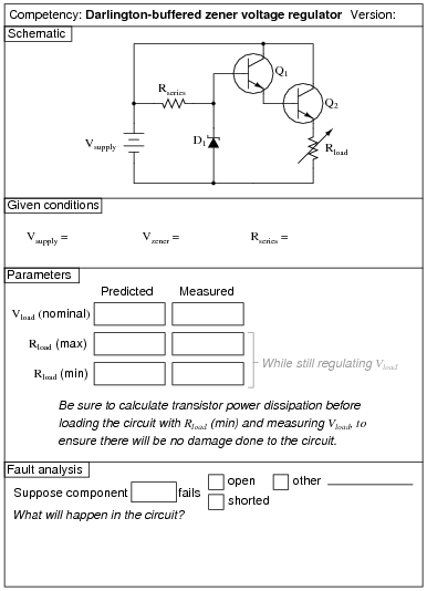
The Rload (max) and Rload (min) parameters are the maximum and minimum resistance settings that Rload may be adjusted to with the regulator circuit maintaining constant load voltage. Vload (nominal) is simply the regulated voltage output of the circuit under normal conditions.
Reveal answerUse circuit simulation software to verify your predicted and measured parameter values.
Notes:Use a variable-voltage, regulated power supply to supply any amount of DC voltage below 30 volts.
I highly recommend specifying a large value for Rseries and/or a high-wattage rated transistor and variable load resistor, so that students do not dissipate excessive power at either the transistor or the load as they test for Rload (min). Do not use a decade resistance box for Rload unless you have made sure its power dissipation will not be exceeded under any circuit condition!
An extension of this exercise is to incorporate troubleshooting questions. Whether using this exercise as a performance assessment or simply as a concept-building lab, you might want to follow up your students’ results by asking them to predict the consequences of certain circuit faults.
-
Question 26 of 62

Reveal answerUse circuit simulation software to verify your predicted and measured parameter values.
Notes:I recommend a 47 kΩ resistor for R1 and a 100 kΩ potentiometer for Rload.
An extension of this exercise is to incorporate troubleshooting questions. Whether using this exercise as a performance assessment or simply as a concept-building lab, you might want to follow up your students’ results by asking them to predict the consequences of certain circuit faults.
-
Question 27 of 62

Reveal answerUse circuit simulation software to verify your predicted and measured parameter values.
Notes:The purpose of this exercise is to get students to understand how AC signals are mixed with DC voltages (“biased”) and also how these DC bias voltages are removed to leave just an AC signal. This is important to understand for the purpose of analyzing BJT amplifier circuits.
Use a variable-voltage, regulated power supply to supply any amount of DC voltage below 30 volts. Specify standard resistor values, all between 1 kΩ and 100 kΩ (1k5, 2k2, 2k7, 3k3, 4k7, 5k1, 6k8, 10k, 22k, 33k, 39k 47k, 68k, etc.). Use a sine-wave function generator to supply an audio-frequency input signal.
An extension of this exercise is to incorporate troubleshooting questions. Whether using this exercise as a performance assessment or simply as a concept-building lab, you might want to follow up your students’ results by asking them to predict the consequences of certain circuit faults.