
 Facebook
 Google
 GitHub
 Linkedin
Discrete Semiconductor Devices and Circuits
Performance-Based Assessments for Semiconductor Circuit Competencies
62 questions By Tony R. Kuphaldt
-
Question 4 of 62
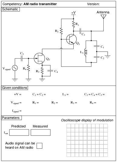
Reveal answerUse circuit simulation software to verify your predicted and measured parameter values.
Notes:I have had great success with the following values:
- V = 7 to 24 volts
- C1 and C2 = 0.001 μF
- C3, C4, and C5 = 0.47 μF
- L1 = 100 μH (ferrite core RF choke)
- R1 = 22 kΩ
- R2 = 1.5 MΩ
- R3 = 6.8 kΩ
- R4 = 100 kΩ
- Q1 = part number 2N3403
- Q2 = part number MPF 102
With these component values, the carrier waveform was quite clean and the frequency was almost exactly 700 kHz:
$$f_{out} = \frac{1}{2{\pi}\sqrt{\frac{LC_1C_2}{C_1+C_2}}}$$
Modulation isn’t that great, due to the crude nature of the circuit, but it is certainly good enough to hear over an appropriately tuned AM radio. Setting Vsignal and fsignal is a matter of experimentation, to achieve the desired degree of modulation and tone pitch.
An extension of this exercise is to incorporate troubleshooting questions. Whether using this exercise as a performance assessment or simply as a concept-building lab, you might want to follow up your students’ results by asking them to predict the consequences of certain circuit faults.
-
Question 5 of 62

Reveal answerUse circuit simulation software to verify your predicted and measured parameter values.
Notes:Use a variable-voltage, regulated power supply to supply any amount of DC voltage below 30 volts. Specify standard resistor values, all between 1 kΩ and 100 kΩ (1k5, 2k2, 2k7, 3k3, 4k7, 5k1, 6k8, 10k, 22k, 33k, 39k 47k, 68k, etc.).
This circuit demonstrates the use of passive integrators to convert a square wave into a pseudo-sine wave output. The multivibrator portion produces nice, sharp-edged square wave signals at the transistor collector terminals when resistors R1 and R4 are substantially smaller than resistors R2 and R3. Component values I’ve used with success are 1 kΩ for R1 and R4, 100 kΩ for R2 and R3, and 0.001 μF for C1 and C2.
Resistors R5 and R6, along with capacitors C3 and C4, form a dual passive integrator network to re-shape the square-wave output of the multivibrator into a pseudo-sine wave. These components’ values must be chosen according to the multivibrator frequency, so that the integration is realistic without the attenuation being excessive. Integrator component values that have worked well for the multivibrator components previously specified are 10 kΩ for R5 and R6, and 0.1 μF for C3 and C4.
Transistor Q3 is just an emitter follower, placed there to give the amplifier section a high input impedance. Q3‘s emitter resistor value is not critical. I have used a 1 kΩ resistor for R7 with good success.
The last transistor (Q4) is for voltage amplification. A “trimmer” style potentiometer (10 kΩ recommended for Rpot) provides easy adjustment of biasing for different supply voltages. Using the potentiometer, I have operated this circuit on supply voltages ranging from -6 volts to -27 volts. Use a bypass capacitor (C7) large enough that its reactance at the operating frequency is negligible (less than 1 ohm is good), such as 33 μF. Resistor values I’ve used with success are 10 kΩ for R8 and 4.7 kΩ for R9. Coupling capacitor values are not terribly important, so long as they present minimal reactance at the operating frequency. I have used 0.47 μF for both C5 and C6 with good success.
You may find that the relatively high operating frequency of this circuit complicates matters with regard to parasitic capacitances. The fast rise and fall times of the strong square wave tend to couple easily to the sine-wave portions of the circuit, especially when the sine wave signal is so severely attenuated by the double integrators. One solution to this dilemma is to lower the operating frequency of the circuit, allowing a lower cutoff frequency for the double integrator (two-pole lowpass filter) section which in turn will improve the signal-to-noise ratio throughout. If you wish to try this, you may use these suggested component values:
- R1 = 1 kΩ
- R2 = 100 kΩ
- R3 = 100 kΩ
- R4 = 1 kΩ
- R5 = 100 kΩ
- R6 = 100 kΩ
- R7 = 1 kΩ
- R8 = 10 kΩ
- R9 = 4.7 kΩ
- Rpot = 10 kΩ
- C1 = 0.047 μF
- C2 = 0.047 μF
- C3 = 0.1 μF
- C4 = 0.047 μF
- C5 = 1 μF
- C6 = 1 μF
- C7 = 33 μF
An extension of this exercise is to incorporate troubleshooting questions. Whether using this exercise as a performance assessment or simply as a concept-building lab, you might want to follow up your students’ results by asking them to predict the consequences of certain circuit faults.
-
Question 6 of 62
Reveal answerUse circuit simulation software to verify your predicted and measured parameter values.
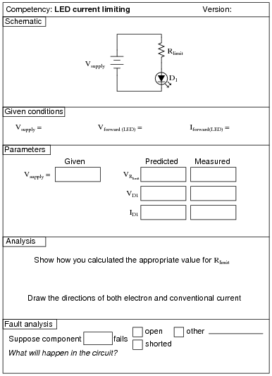
Notes:Use a variable-voltage, regulated power supply to supply any amount of DC voltage below 30 volts. Have students calculate the necessary current-limiting resistor for their LEDs based on measured values of Vforward for the LED (using a multimeter with a “diode-check” function). Let students research the typical forward current for their LED from an appropriate datasheet. Any LED should suffice for this activity.
An extension of this exercise is to incorporate troubleshooting questions. Whether using this exercise as a performance assessment or simply as a concept-building lab, you might want to follow up your students’ results by asking them to predict the consequences of certain circuit faults.


