Facebook
 Google
 GitHub
 Linkedin
Discrete Semiconductor Devices and Circuits
Performance-Based Assessments for Semiconductor Circuit Competencies
62 questions By Tony R. Kuphaldt
-
Question 40 of 62
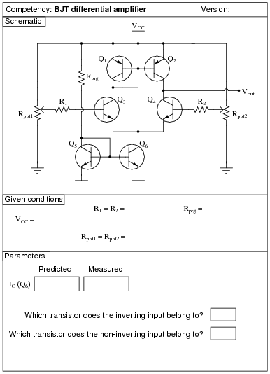
Reveal answerUse circuit simulation software to verify your predicted and measured parameter values.
Notes:Use a variable-voltage, regulated power supply to supply any amount of DC voltage below 30 volts. Specify standard resistor values, all between 1 kΩ and 100 kΩ (1k5, 2k2, 2k7, 3k3, 4k7, 5k1, 6k8, 10k, 22k, 33k, 39k 47k, 68k, etc.).
I suggest using ordinary (general-purpose) signal transistors in this circuit, such as the 2N2222 and 2N3403 (NPN), and the 2N2907 and 2N3906 (PNP) models, operating with a VCC of 12 volts. When constructed as shown, this circuit has sufficient gain to be used as a crude operational amplifier (connect the inverting input to the output through various feedback networks).
These values have worked well for me:
- VCC = 12 volts
- R1 = 10 kΩ
- R2 = 10 kΩ
- Rprg = 10 kΩ
- Rpot1 = 10 kΩ
- Rpot2 = 10 kΩ
I recommend instructing students to set each potentiometer near its mid-position of travel, then slightly adjusting each one to see the sharp change in output voltage as one input voltage crosses the other. If students wish to monitor each of the input voltages to check for a condition of crossing, they should measure right at the transistor base terminals, not at the potentiometer wiper terminals, so as to not incur error resulting from current through protection resistors R1 or R2.
An extension of this exercise is to incorporate troubleshooting questions. Whether using this exercise as a performance assessment or simply as a concept-building lab, you might want to follow up your students’ results by asking them to predict the consequences of certain circuit faults.
-
Question 41 of 62
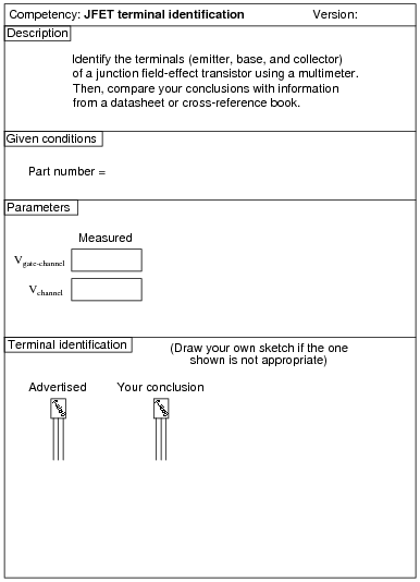
Reveal answerContrary to what you might think, the datasheet or cross-reference is not the “final authority” for checking your meter-based conclusions! I have seen datasheets and cross-reference manuals wrong more than once!
Notes:Identification of JFET terminals is a very important skill for technicians to have. Most modern multimeters have a diode check feature which may be used to positively identify PN junction polarities, and this is what I recommend students use for identifying JFET terminals.
To make this a really good performance assessment, you might want to take several JFET’s and scratch the identifying labels off, so students cannot refer to memory for pin identification (for instance, if they remember the pin assignments of a J309 because they use it so often). Label these transistors with your own numbers (“1”, “2”, etc.) so you will know which is which, but not the students!
-
Question 42 of 62

Reveal answerUse circuit simulation software to verify your predicted and measured parameter values.
Notes:I strongly recommend a value for R1 of 1 MΩ or more, to protect the JFET gate from overcurrent damage. The students will calculate their own dropping resistor value, based on the supply voltage and the LED ratings.
This exercise lends itself to experimentation with static electricity. The input impedance of an average JFET is so high that the LED may be made to turn on and off with just a touch of the probe wire to a charged object (such as a person).
Using only the components shown, students may not be able to get their JFETs to completely turn off. This is left for them as a challenge to figure out!
I expect students to be able to figure out how to calculate the transistor’s power dissipation without being told what measurements to take!