Facebook
 Google
 GitHub
 Linkedin
Discrete Semiconductor Devices and Circuits
Performance-Based Assessments for Semiconductor Circuit Competencies
62 questions By Tony R. Kuphaldt
-
Question 46 of 62

Reveal answerUse circuit simulation software to verify your predicted and measured parameter values.
Notes:An extension of this exercise is to incorporate troubleshooting questions. Whether using this exercise as a performance assessment or simply as a concept-building lab, you might want to follow up your students’ results by asking them to predict the consequences of certain circuit faults.
-
Question 47 of 62
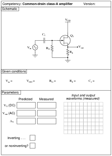
Reveal answerUse circuit simulation software to verify your predicted and measured parameter values.
Notes:Use a variable-voltage, regulated power supply to supply any amount of DC voltage below 30 volts. Specify standard resistor values, all between 1 kΩ and 100 kΩ (1k5, 2k2, 2k7, 3k3, 4k7, 5k1, 6k8, 10k, 22k, 33k, 39k 47k, 68k, etc.). Use a sine-wave function generator to supply an audio-frequency input signal, and make sure its amplitude isn’t set so high that the amplifier clips.
I have had good success using the following values:
- VDD = 9 volts
- Vin = 1 volt (peak), f = 2 kHz
- RG = 100 kΩ
- RS = 10 kΩ
- C1 = 0.47 μF
Please note that the quiescent output voltage is impossible to precisely predict, as it depends on the particular characteristics of the JFET used (ID versus VGS). The fact that this circuit uses self-biasing instead of voltage divider biasing makes the situation worse. Predicting quiescent gate voltage, however should be extremely easy (0 volts) if one understands how JFETs function.
An interesting parameter to explore in this circuit is the effect of the source resistor value on voltage gain. The theoretical voltage gain of a simple common-drain amplifier circuit is unity (1), but this may be approximated only with relatively large load resistor (RS) values. Try substituting a 1 kΩ or less resistor for RS, and notice what happens to the gain. Then, have your students explain why this happens!
An extension of this exercise is to incorporate troubleshooting questions. Whether using this exercise as a performance assessment or simply as a concept-building lab, you might want to follow up your students’ results by asking them to predict the consequences of certain circuit faults.
-
Question 48 of 62
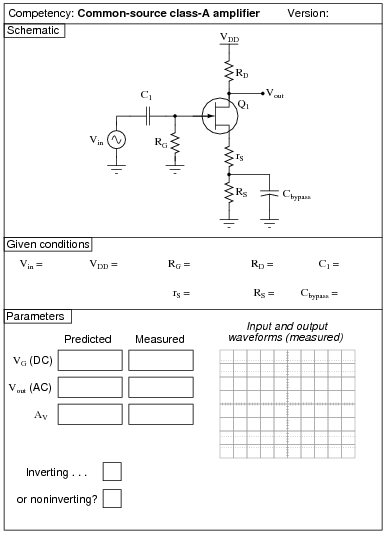
Reveal answerUse circuit simulation software to verify your predicted and measured parameter values.
Notes:Use a variable-voltage, regulated power supply to supply any amount of DC voltage below 30 volts. Specify standard resistor values, all between 1 kΩ and 100 kΩ (1k5, 2k2, 2k7, 3k3, 4k7, 5k1, 6k8, 10k, 22k, 33k, 39k 47k, 68k, etc.). Use a sine-wave function generator to supply an audio-frequency input signal, and make sure its amplitude isn’t set so high that the amplifier clips.
I have had good success using the following values:
- VDD = 12 volts
- Vin = 0.5 volt (peak-to-peak), f = 2 kHz
- RG = 100 kΩ
- rS = 2.2 kΩ
- RS = 10 kΩ
- RD = 10 kΩ
- C1 = 0.47 μF
- Cbypass = 10 μF
Please note that the quiescent output voltage is impossible to precisely predict, as it depends on the particular characteristics of the JFET used (ID versus VGS). The fact that this circuit uses self-biasing instead of voltage divider biasing makes the situation worse. Predicting quiescent gate voltage, however should be extremely easy (0 volts) if one understands how JFETs function.
All quiescent circuit values depend on VDD, so if things aren’t biased the way you would like, simply adjust the power supply voltage to suit.
An extension of this exercise is to incorporate troubleshooting questions. Whether using this exercise as a performance assessment or simply as a concept-building lab, you might want to follow up your students’ results by asking them to predict the consequences of certain circuit faults.