Facebook
 Google
 GitHub
 Linkedin
Discrete Semiconductor Devices and Circuits
Performance-Based Assessments for Semiconductor Circuit Competencies
62 questions By Tony R. Kuphaldt
-
Question 13 of 62
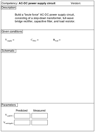
Reveal answerUse circuit simulation software to verify your predicted and measured parameter values.
Notes:Use a Variac at the test bench to provide variable-voltage AC power for the students’ power supply circuits.
An extension of this exercise is to incorporate troubleshooting questions. Whether using this exercise as a performance assessment or simply as a concept-building lab, you might want to follow up your students’ results by asking them to predict the consequences of certain circuit faults.
-
Question 14 of 62
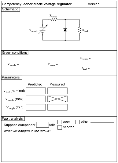
The Vsupply (min) parameter is the minimum voltage setting that Vsupply may be adjusted to with the regulator circuit maintaining constant load voltage at Rload. Vsupply (max) is the maximum voltage that Vsupply may be adjusted to without exceeding the zener diode’s power rating. Vload (nominal) is simply the regulated voltage output of the circuit under normal conditions.
Reveal answerUse circuit simulation software to verify your predicted and measured parameter values.
Notes:Use a variable-voltage, regulated power supply to supply any amount of DC voltage below 30 volts. Specify standard load resistor values, all between 1 kΩ and 100 kΩ (1k5, 2k2, 2k7, 3k3, 4k7, 5k1, 6k8, 10k, 22k, 33k, 39k 47k, 68k, etc.), and let the students determine the proper resistance values for their series dropping resistors.
I recommend specifying a series resistor value (Rseries) high enough that there will little danger in damaging the zener diode due to excessive supply voltage, but also low enough so that the normal operating current of the zener diode is great enough for it to drop its rated voltage. If Rseries is too large, the zener diode’s current will be too small, resulting in lower than expected voltage drop and poorer regulation (operating near the flatter end of the characteristic curve).
Values I have used with success are as follows:
- Rseries = 1 kΩ
- Rload = 10 kΩ
- Vzener = 5.1 volts (diode part number 1N4733)
- Vsupply = 12 volts
Measuring the minimum supply voltage is a difficult thing to do, because students must look for a point where the output voltage begins to directly follow the input voltage (going down) instead of holding relatively stable. One interesting way to measure the rate of output voltage change is to set a DMM on the AC voltage setting, then use that to measure Vload as Vsupply is decreased. While turning the voltage adjustment knob on Vsupply at a steady rate, students will look for an increase in AC voltage (a greater rate of change) at Vload. Essentially, what students are looking for is the point where \(\frac{dV_{load}}{dV_{supply}}\) begins to increase.
An extension of this exercise is to incorporate troubleshooting questions. Whether using this exercise as a performance assessment or simply as a concept-building lab, you might want to follow up your students’ results by asking them to predict the consequences of certain circuit faults.
-
Question 15 of 62
Reveal answerUse circuit simulation software to verify your predicted and measured parameter values.
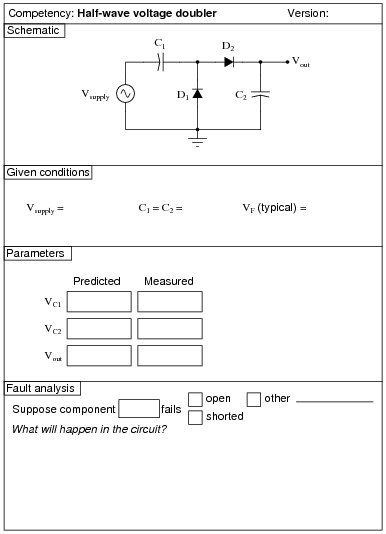
Notes:I’ve used 47 μF electrolytic capacitors and 1N4001 diodes with good success on a 10 volt AC (RMS) power supply. I recommend that students measure their own diodes to determine typical forward voltage (VF).
Don’t forget to mention the polarity sensitivity of these capacitors! Electrolytic capacitors can explode violently if reverse-connected!