Facebook
 Google
 GitHub
 Linkedin
Discrete Semiconductor Devices and Circuits
Performance-Based Assessments for Semiconductor Circuit Competencies
62 questions By Tony R. Kuphaldt
-
Question 10 of 62
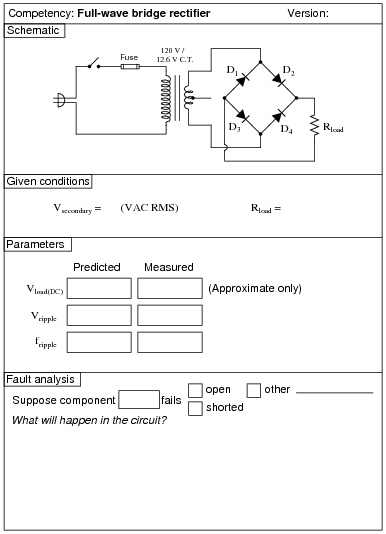
Reveal answerUse circuit simulation software to verify your predicted and measured parameter values.
Notes:I recommend using 1N400X series rectifying diodes for all rectifier circuit designs. Make sure that the resistance value you specify for your load is not so low that the resistor’s power dissipation is exceeded.
Watch out for harmonics in the power line voltage creating problems with RMS/peak voltage relationships. If this is a problem, try using a ferroresonant transformer to filter out some of the harmonic content. Do not try to use a sine-wave signal generator as an alternate source of AC power, because most signal generators have internal impedances that are much too high for such a task.
It is difficult to precisely calculate the DC load voltage from a rectifier circuit such as this when the transformer secondary voltage is relatively low. The diodes’ forward voltage drop essentially distorts the rectified waveform so that it is not quite the same as what you would expect a full-wave rectified waveform to be:
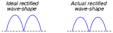
Accurate calculation of the actual rectified wave-shape’s average voltage value requires integration of the half-sine peak over a period less than π radians, which may very well be beyond the capabilities of your students. This is why I request approximations only on this parameter.
One approximation that works fairly well is to take the AC RMS voltage, convert it to average voltage (multiply by 0.9), and then subtract the total forward junction voltage lost by the diode (0.7 volts per diode typical for silicon, for a total of 1.4 volts).
An extension of this exercise is to incorporate troubleshooting questions. Whether using this exercise as a performance assessment or simply as a concept-building lab, you might want to follow up your students’ results by asking them to predict the consequences of certain circuit faults.
-
Question 11 of 62

Reveal answerUse circuit simulation software to verify your predicted and measured parameter values.
Notes:I recommend using 1N400X series rectifying diodes for all rectifier circuit designs. Make sure that the resistance value you specify for your load is not so low that the resistor’s power dissipation is exceeded.
Watch out for harmonics in the power line voltage creating problems with RMS/peak voltage relationships. If this is a problem, try using a ferroresonant transformer to filter out some of the harmonic content. Do not try to use a sine-wave signal generator as an alternate source of AC power, because most signal generators have internal impedances that are much too high for such a task.
It is difficult to precisely calculate the DC load voltage from a rectifier circuit such as this when the transformer secondary voltage is relatively low. The diodes’ forward voltage drop essentially distorts the rectified waveform so that it is not quite the same as what you would expect a full-wave rectified waveform to be:

Accurate calculation of the actual rectified wave-shape’s average voltage value requires integration of the half-sine peak over a period less than π radians, which may very well be beyond the capabilities of your students. This is why I request approximations only on this parameter.
One approximation that works fairly well is to take the AC RMS voltage (in this case, half of the secondary winding’s output, since this is a center-tap design), convert it to average voltage (multiply by 0.9), and then subtract the forward junction voltage lost by the diode (0.7 volts typical for silicon).
An extension of this exercise is to incorporate troubleshooting questions. Whether using this exercise as a performance assessment or simply as a concept-building lab, you might want to follow up your students’ results by asking them to predict the consequences of certain circuit faults.
-
Question 12 of 62

Reveal answerUse circuit simulation software to verify your predicted and measured parameter values.
Notes:I recommend using 1N400X series rectifying diodes for all rectifier circuit designs. Make sure that the resistance value you specify for your load is not so low that the resistor’s power dissipation is exceeded.
An extension of this exercise is to incorporate troubleshooting questions. Whether using this exercise as a performance assessment or simply as a concept-building lab, you might want to follow up your students’ results by asking them to predict the consequences of certain circuit faults.