Facebook
 Google
 GitHub
 Linkedin
AC Electric Circuits
Series and Parallel AC Circuits
75 questions By Tony R. Kuphaldt
-
Question 55 of 75
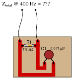
Calculate the total impedance of this RC circuit, once using nothing but scalar numbers, and again using complex numbers:
Reveal answerScalar calculations
R1 = 7.9 kΩ GR1 = 126.6 μS
XC1 = 8.466 kΩ BC1 = 118.1 μS
Ytotal = √{G2 B2} = 173.1 μS
Ztotal = [1/(Ytotal)] = 5.776 kΩ
Complex number calculations
R1 = 7.9 kΩ ZR1 = 7.9 kΩ ∠ 0o
XC1 = 8.466 kΩ ZC1 = 8.466 kΩ ∠−90o
Ztotal = [ 1/([1/(ZR1)] [1/(ZC1)])] = 5.776 kΩ ∠−43.02o
Notes:Some electronics textbooks (and courses) tend to emphasize scalar impedance calculations, while others emphasize complex number calculations. While complex number calculations provide more informative results (a phase shift given in every variable!) and exhibit conceptual continuity with DC circuit analysis (same rules, similar formulae), the scalar approach lends itself better to conditions where students do not have access to calculators capable of performing complex number arithmetic. Yes, of course, you can do complex number arithmetic without a powerful calculator, but it’s a lot more tedious and prone to errors than calculating with admittances, susceptances, and conductances (primarily because the phase shift angle is omitted for each of the variables).
-
Question 56 of 75
Calculate the total impedance offered by these two capacitors to a sinusoidal signal with a frequency of 900 Hz:

Show your work using three different problem-solving strategies:
- Calculating total capacitance (Ctotal) first, then total impedance (Ztotal).
- Calculating individual admittances first (YC1 and YC2), then total admittance (Ytotal), then total impedance (Ztotal).
- Using complex numbers: calculating individual impedances first (ZC1 and ZC2), then total impedance (Ztotal).
Do these two strategies yield the same total impedance value? Why or why not?
Reveal answerFirst strategy:
Ctotal = 0.43 μF
Xtotal = 411.3 Ω
Ztotal = 411.3 Ω ∠−90o or Ztotal = 0 − j411.3 Ω
Second strategy:
ZC1 = XC1 = 535.9 Ω
YC1 = [1/(ZC1)] = 1.866 mS
ZC1 = XC2 = 1.768 kΩ
YC2 = [1/(ZC2)] = 565.5 μS
Ytotal = 2.432 mS
Ztotal = [1/(Ytotal)] = 411.3 Ω
Third strategy: (using complex numbers)
XC1 = 535.9 Ω ZC1 = 535.9 Ω ∠−90o
XC2 = 1.768 kΩ ZC1 = 1.768 kΩ ∠−90o
Ztotal = 411.3 Ω ∠−90o or Ztotal = 0 − j411.3 Ω
Notes:A common misconception many students have about capacitive reactances and impedances is that they must interact “oppositely” to how one would normally consider electrical opposition. That is, many students believe capacitive reactances and impedances should add in parallel and diminish in series, because that’s what capacitance (in Farads) does! This is not true, however. Impedances always add in series and diminish in parallel, at least from the perspective of complex numbers. This is one of the reasons I favor AC circuit calculations using complex numbers: because then students may conceptually treat impedance just like they treat DC resistance.
The purpose of this question is to get students to realize that any way they can calculate total impedance is correct, whether calculating total capacitance and then calculating impedance from that, or by calculating the impedance of each capacitor and then combining impedances to find a total impedance. This should be reassuring, because it means students have a way to check their work when analyzing circuits such as this!
-
Question 57 of 75
Due to the effects of a changing electric field on the dielectric of a capacitor, some energy is dissipated in capacitors subjected to AC. Generally, this is not very much, but it is there. This dissipative behavior is typically modeled as a series-connected resistance:

Calculate the magnitude and phase shift of the current through this capacitor, taking into consideration its equivalent series resistance (ESR):

Compare this against the magnitude and phase shift of the current for an ideal 0.22 μF capacitor.
Reveal answerI = 3.732206 mA ∠ 89.89o for the real capacitor with ESR.
I = 3.732212 mA ∠ 90.00o for the ideal capacitor.
Follow-up question #1: can this ESR be detected by a DC meter check of the capacitor? Why or why not?
Follow-up question #2: explain how the ESR of a capacitor can lead to physical heating of the component, especially under high-voltage, high-frequency conditions. What safety concerns might arise as a result of this?
Notes:Although capacitors do contain their own parasitic effects, ESR being one of them, they still tend to be much “purer” components than inductors for general use. This is another reason why capacitors are generally favored over inductors in applications where either will suffice.